00195440-05-SG_D-Series_FSE-EN.pdf - 第152页
9 C&P Placement Heads 9.1 Overview 9.1.6 Throughput Test for Vacuum Holding Circuit 152 Student Guide SIPLACE D-Series (FSE) ▪ Position the Z axis downwards , touch the nozzle tip and p ress upwards. The LB 'Z d…
9 C&P Placement Heads
9.1.5 Compressed Air Supply on C&P Head 9.1 Overview
Student Guide SIPLACE D-Series (FSE) 151
▪ Ein zusätzlicher Z-Höhencheck der die Abholhöhe für Pipetten 925 und 914/904 oder kleiner prüft:
ModeZAxisCheck="2" – Es wird die Fehlermeldung 3573 "Pipette verschmutzt bzw. Hindernis beim
Abholen." ausgegeben.
HeightZAxisMin="200"
HeightZAxisMax="1000"
Wird die theoretische Abholhöhe um mehr als z. B. 200 µm (vom Typ der Pipette abhängig) unter-
schritten (Zielposition nicht erreicht/höher), so reagiert die Stationssoftware mit der Fehlermeldung
3573 "Pipette verschmutzt bzw. Hindernis beim Abholen.". Die Pipette wird gereinigt und versucht,
das Bauelement nochmals abzuholen.
9.1.5
9.1.5 Compressed Air Supply on C&P Head
Compressed Air Supply on C&P Head
The compressed air for D1/D1i/D2/D2i machines is distributed via an additional T-piece and small com-
ponent sets with pneumatic hoses to the two placement heads.
9.1.5.1
9.1.5.1 Vacuum Generator
Vacuum Generator
9.1.5.2
9.1.5.2 Placement Head Function Check
Placement Head Function Check
Before the 1st reference run or with released Z and star axis:
Check Z axis:
▪ Rotate the star so that one segment is in the star pickup/place position.
▪ Position the Z axis up and down on the belt. The LED light barrier (LB) Z up will shine (down) or ex-
tinguish (up).
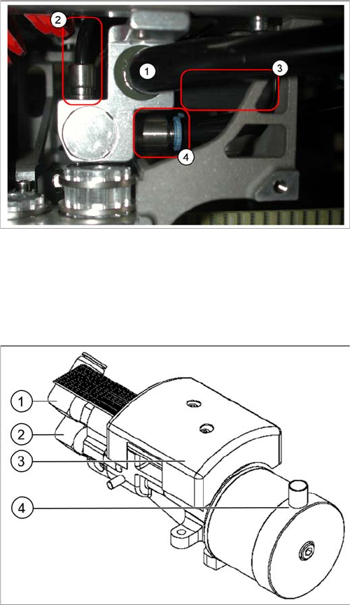
Pneumatic distributor under the gantry head distributor
Legend
1. Input: Exhaust Venturi nozzle pneumatic hose
(PK12)
2. Input: 7-fold pneumatic hose (PK 5)
3. Silencer for exhaust (only indicated in the diagram)
4. Compressed air outlet for pickup/placement circuit
and holding circuit
D1/D1i/D2/D2i: to T distributor C&P/P&P head
D4/D4i: to C&P head
Vacuum generator
Legend
1. Hold circuit supply
2. Placement and pickup circuit for blast air supply
3. Vacuum measuring board
4. Discharged air from the vacuum generator to the si-
lencer in the compressed air distributor

9 C&P Placement Heads
9.1 Overview 9.1.6 Throughput Test for Vacuum Holding Circuit
152 Student Guide SIPLACE D-Series (FSE)
▪ Position the Z axis downwards, touch the nozzle tip and press upwards. The LB 'Z down' will shine
and both LEDs will shine until the Z axis is pulled up again.
Check the stepping motor for swiveling in the turning station:
▪ Touch the turning station cam disk on the right side of the head with your finger and rotate it. The 'LB
DP' LED will shine and extinguish with the scan rhythm of the cam disk.
Check the stepping motors of the valve positioning drives:
▪ Feel along the bottom of the placement head from the right side and touch the cam disk upwards in
the pickup/place position.
▪ When rotated, the LB "ZH" shines and extinguishes with the scan rhythm of the cam disk.
▪ Feel along the bottom of the placement head from the left side and touch the cam disk upwards in
the reject position.
▪ When rotated, the LB "BA" shines and extinguishes with the scan rhythm of the cam disk.
9.1.6
9.1.6 Throughput Test for Vacuum Holding Circuit
Throughput Test for Vacuum Holding Circuit
Through the installation of the placement head, the silicon tube for supplying the holding circuit with vac-
uum can become jammed, especially in HF/X/D3 machines.
The lower throughput reduces the holding force for the components during the placement process. This
means that components can be displaced on the nozzle, both before and after the component camera.
If this happens before the camera, the component may be moved out of the pickup tolerance. After the
camera, displacement can lead to random, uncorrectable placement offsets.
This fault can be recognized with the SITEST 'throughput test".
C&P12/6
Perform the following steps:
► Return all C&P head nozzles.
► Measure the holding circuit vacuum. Typical values are around 900 mbar (values over 900 are
shown as 900).
► Open a segment in the reject circuit and
► step the star one position.
► Measure the holding circuit vacuum. Values around or higher than 800 mbar are OK.
► Open another segment in the reject circuit and
► step the star one position.
► Measure the holding circuit vacuum. Values higher than 700 mbar are OK.
Values around 600 mbar are reached at around half the diameter of the silicon supply tube.
Vacuum values in the holding circuit which only reach 500 mbar are no longer sufficient to guarantee the
holding circuit function. (Values under 400 mbar are only shown as -1)
Gemessen wurde hier jeweils ohne Pipetten.
Description Vakuumwerte für die Segmente 1 bis 8
Offene Segmente im
Haltekreis
012345678
Vakuum Haltekreis OK -900 -830 -756 -620 -532 -460 -412 1
Schlauch für Haltekreis leicht
eingequetscht
-900 -800 -674 -532 -428 1 1 1
Schlauch für Haltekreis
eingequetscht
-900 -621 -420 1
Große Probleme Haltekreis -900 -410 1 1
9 C&P Placement Heads
9.1.7 Overview of Blast Air Supply 9.1 Overview
Student Guide SIPLACE D-Series (FSE) 153
9.1.7
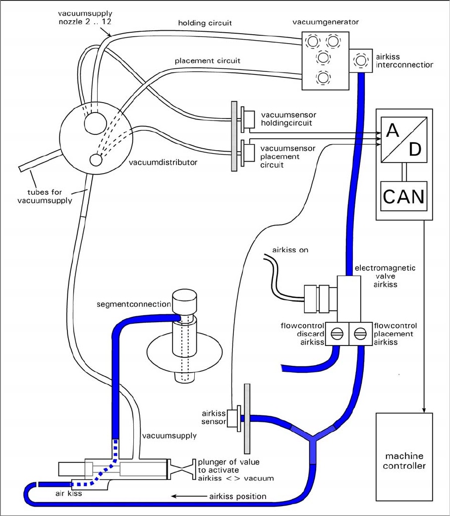
9.1.7 Overview of Blast Air Supply
Overview of Blast Air Supply
General overview of the blast air function