00195440-05-SG_D-Series_FSE-EN.pdf - 第155页
9 C&P Placement Heads 9.2.1 Working Position on Placement Head 9.2 Placement Procedure Student Guide SIPLACE D-Series (FSE) 155 ▪ Valve plunger p ulled (towards back): the connection to the vac uum supply exists, eve…
9 C&P Placement Heads
9.1 Overview 9.1.8 Overview of Vacuum Supply
154 Student Guide SIPLACE D-Series (FSE)
9.1.8
9.1.8 Overview of Vacuum Supply
Overview of Vacuum Supply
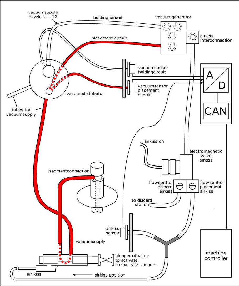
General overview of the vacuum function
9.1.9
9.1.9 Air Blast and Vacuum Supply - Description
Air Blast and Vacuum Supply - Description
The two diagrams show that there are 3 states for air supply to the segments.
▪ Elektromagnet-Ventil "Blasluft" EIN & Ventilstößel innen: air blast is present at the segment for
placement (reject).
▪ Elektromagnet-Ventil "Blasluft" AUS & Ventilstößel innen: the segment is airtight i.e. it is cut off from
the air blast and vacuum supplies.
Dies ist die Stellung für die Vakuummessung. D. h. es wird die Dichtwirkung des Stößels gemessen.
Die Schlauch und Rohrstücke zur Pipette hin werden nie überprüft (siehe folgendes Kapitel).
9 C&P Placement Heads
9.2.1 Working Position on Placement Head 9.2 Placement Procedure
Student Guide SIPLACE D-Series (FSE) 155
▪ Valve plunger pulled (towards back): the connection to the vacuum supply exists, even if the elec-
tromagnetic valve is switched on.
This function description illustrates that the valve plunger is the element with the greatest influence on
the placement and pickup reliability. It is therefore important to maintain this key part with the tools spe-
cially developed for this purpose.
9.2
9.2 Placement Procedure
Placement Procedure
9.2.1
9.2.1 Working Position on Placement Head
Working Position on Placement Head
9.2.2
9.2.2 C&P12 in Basic Setting Star 15°
C&P12 in Basic Setting Star 15°
9.2.3
9.2.3 Boards – Position Recognition
Boards – Position Recognition
Board position recognition is used to determine the exact position of the board in the machine (conveyor
--> placement area). There should be at least two fiducials on the board. These are then used to calcu-
lated the X/Y position and the rotary angle of the board, in the conveyor system. A maximum of 3 fiducials
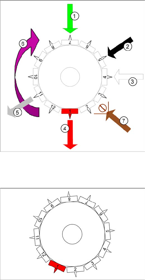
Working position on placement head
Legend
1. optical centering
2. Turning station / DLM2
3. Service position for segment: check/remove the noz-
zles and sleeves
4. Pick and place station (also reject position for D3/D2/
D2i/D1/D1i)
5. Reject position for D1/D1i/D2/D2i/D4/D4i machines
only
6. Direction of operation
7. Position of component sensor option (only C&P12)
C&P12 in basic setting star 15°
Star position:
Digits: 15000
Angle 15°
1° is equivalent to 1000 digits
This is the basic C&P12 setting. When the X and Y axes
are in the waiting position, the star axis is rotated into this
basic setting.

9 C&P Placement Heads
9.2 Placement Procedure 9.2.3 Boards – Position Recognition
156 Student Guide SIPLACE D-Series (FSE)
can be programmed for position recognition. The fiducials should not be on the same line as one anoth-
er. In addition to determining the position of the board in the conveyor system, this 3rd fiducial enables
you to determine and correct any displacement within the board (jolted, stretched).
9.2.3.1
9.2.3.1 Temperature Compensation
Temperature Compensation
In addition to board recognition, SIPLACE D/Di-series machines perform temperature compensation
with the 2nd gantry in the placement area, through PCB position recognition. This compensates another
error source which could affect accuracy.
9.2.3.2
9.2.3.2 PCB Position Recognition - Centering the PCB Fiducials
PCB Position Recognition - Centering the PCB Fiducials
Board recognition in SIPLACE D4/D4i
Legend
1. Gantry 1
2. Gantry 2
3. Gantry 3
4. Gantry 4
5. Transport direction
Gantry 4: position recognition with max. 3 fiducials,
Gantry 2: position recognition with max. 2 fiducials, in PA
2 of D4/D4i
Gantries 1 and 3: Temperature compensation by ap-
proaching the fiducials - a position difference to gantry 4
or 2 is recognized by the Vision system and is then taken
into account and compensated in the following placement
procedure.
Grobzentrierschritt zur Markenzentrierung
A fiducial is expected at this target position. The PCB
camera moves out of the waiting position to this fiducial
position.
▪ PCB position recognition is performed, generally be-
fore the gantry takes up the 1st component.
▪ The gantry axes move the PCB camera to the theo-
retical fiducial position. The camera records an image
of the 1st fiducial. The Vision system calculates the
center position.