00195440-05-SG_D-Series_FSE-EN.pdf - 第156页
9 C&P Placement Heads 9.2 Placement Procedure 9.2.3 Boards – Position Recognition 156 Student Guide SIPLACE D-Series (FSE) can be programmed for position recognition . The fidu cials shoul d not be on the same line a…
9 C&P Placement Heads
9.2.1 Working Position on Placement Head 9.2 Placement Procedure
Student Guide SIPLACE D-Series (FSE) 155
▪ Valve plunger pulled (towards back): the connection to the vacuum supply exists, even if the elec-
tromagnetic valve is switched on.
This function description illustrates that the valve plunger is the element with the greatest influence on
the placement and pickup reliability. It is therefore important to maintain this key part with the tools spe-
cially developed for this purpose.
9.2
9.2 Placement Procedure
Placement Procedure
9.2.1
9.2.1 Working Position on Placement Head
Working Position on Placement Head
9.2.2
9.2.2 C&P12 in Basic Setting Star 15°
C&P12 in Basic Setting Star 15°
9.2.3
9.2.3 Boards – Position Recognition
Boards – Position Recognition
Board position recognition is used to determine the exact position of the board in the machine (conveyor
--> placement area). There should be at least two fiducials on the board. These are then used to calcu-
lated the X/Y position and the rotary angle of the board, in the conveyor system. A maximum of 3 fiducials
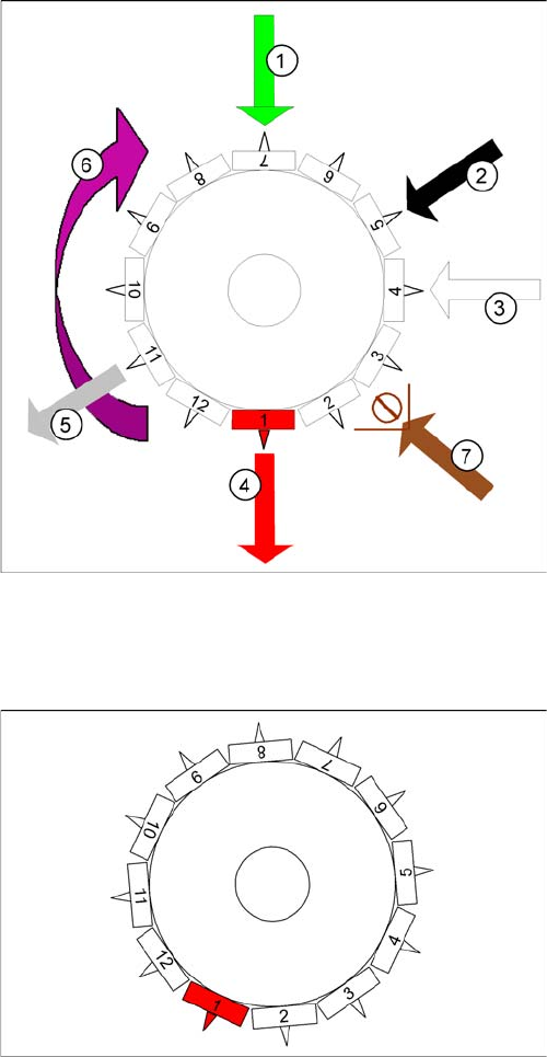
Working position on placement head
Legend
1. optical centering
2. Turning station / DLM2
3. Service position for segment: check/remove the noz-
zles and sleeves
4. Pick and place station (also reject position for D3/D2/
D2i/D1/D1i)
5. Reject position for D1/D1i/D2/D2i/D4/D4i machines
only
6. Direction of operation
7. Position of component sensor option (only C&P12)
C&P12 in basic setting star 15°
Star position:
Digits: 15000
Angle 15°
1° is equivalent to 1000 digits
This is the basic C&P12 setting. When the X and Y axes
are in the waiting position, the star axis is rotated into this
basic setting.

9 C&P Placement Heads
9.2 Placement Procedure 9.2.3 Boards – Position Recognition
156 Student Guide SIPLACE D-Series (FSE)
can be programmed for position recognition. The fiducials should not be on the same line as one anoth-
er. In addition to determining the position of the board in the conveyor system, this 3rd fiducial enables
you to determine and correct any displacement within the board (jolted, stretched).
9.2.3.1
9.2.3.1 Temperature Compensation
Temperature Compensation
In addition to board recognition, SIPLACE D/Di-series machines perform temperature compensation
with the 2nd gantry in the placement area, through PCB position recognition. This compensates another
error source which could affect accuracy.
9.2.3.2
9.2.3.2 PCB Position Recognition - Centering the PCB Fiducials
PCB Position Recognition - Centering the PCB Fiducials
Board recognition in SIPLACE D4/D4i
Legend
1. Gantry 1
2. Gantry 2
3. Gantry 3
4. Gantry 4
5. Transport direction
Gantry 4: position recognition with max. 3 fiducials,
Gantry 2: position recognition with max. 2 fiducials, in PA
2 of D4/D4i
Gantries 1 and 3: Temperature compensation by ap-
proaching the fiducials - a position difference to gantry 4
or 2 is recognized by the Vision system and is then taken
into account and compensated in the following placement
procedure.
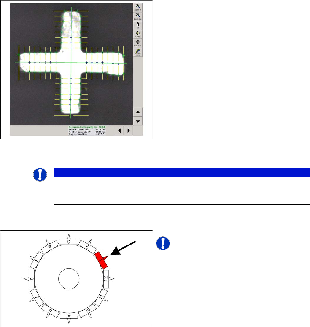
Grobzentrierschritt zur Markenzentrierung
A fiducial is expected at this target position. The PCB
camera moves out of the waiting position to this fiducial
position.
▪ PCB position recognition is performed, generally be-
fore the gantry takes up the 1st component.
▪ The gantry axes move the PCB camera to the theo-
retical fiducial position. The camera records an image
of the 1st fiducial. The Vision system calculates the
center position.
9 C&P Placement Heads
9.2.4 Preparing Nozzle 1 - Moving to Pickup Angle (0° or 90°) 9.2 Placement Procedure
Student Guide SIPLACE D-Series (FSE) 157
9.2.4
9.2.4 Preparing Nozzle 1 - Moving to Pickup Angle (0°or90°)
Preparing Nozzle 1 - Moving to Pickup Angle (0° or 90°)
Feinzentrierschritt zur Markenzentrierung und Markenpo
-
sitionsbestimmung
The centered fiducial now defines the actual position of
the board.
▪ The camera takes a shot of the 2nd fiducial and the
Vision system calculates the center of the image.
▪ A second calculation detects any deviation between
the target fiducial position and the position actually
determined.
▪ All PCB fiducials are optically centered using this
method.
▪ This data is then sent to the machine controller.
▪ The corrected values are then used for the X/Y and
angle positions of the board.
▪ The gantry axes now move the placement head to the
first pickup position.
NOTICE
SIPLACE Vision or synthetic fiducials
If synthetic fiducials are used, this does not change the procedure described; although inkspot
recognition is performed after fiducial recognition.
Rotating nozzle 1 to pickup angle (0° or 90°)
NOTICE! This step is only performed indepen-
dently before the very first pickup cycle.
▪ The star axis rotates to 240°. Nozzle 1 is now in the
DP station.
▪ The DP station swivels in and the DP axis control sys-
tem rotates the nozzle to its pickup angle of 0° or 90°
(default pickup angle).
▪ As soon as the nozzle reaches its position, an end
position signal is emitted and the DP station swivels
back.
The other nozzles on the head are then moved into their
pickup angles by further rotation of the star.