00195440-05-SG_D-Series_FSE-EN.pdf - 第160页
9 C&P Placement Heads 9.2 Placement Procedure 9.2.10 Detailed rotation of DP station, 3. Swivel Out 160 Student Guide SIPLACE D-Series (FSE) 9.2.10 9 . 2 . 1 0 D e t a ile d r o t a t io n o f D P s t a t io n , 3 . …
9 C&P Placement Heads
9.2.8 Positioning into Pickup Angle 9.2 Placement Procedure
Student Guide SIPLACE D-Series (FSE) 159
9.2.8
9.2.8 Positioning into Pickup Angle
Positioning into Pickup Angle
9.2.9
9.2.9 Positioning into Placement Angle
Positioning into Placement Angle
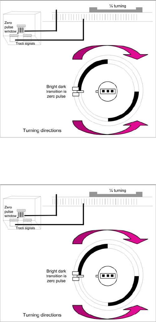
Detailed rotation of DP station, positioning into pickup an
-
gle
▪ The DP axis positions the segment to the relevant
zero pulse and checks the signal level at a distance
of 3 digits.
▪ An end position signal is emitted if the actual position
deviation is within the permitted tolerance.
▪ There is no difference between the 0° and 180° or 90°
and 90° pickup angle.
Detailed rotation process at DP station, positioning into
placement angle
▪ When positioning begins, the actual position of the
axis is set to 0 by setting the position counter of the
DP axis to 0.
▪ The DP drive is operated in relative positioning mode.
▪ The DP axis starts to move towards the target posi-
tion which is calculated from the station calibration
values, the line computer programming values and
the centering values of the placement procedure.
▪ An end position signal is emitted as soon as the actu-
al position deviation is within the permitted tolerance.
9 C&P Placement Heads
9.2 Placement Procedure 9.2.10 Detailed rotation of DP station, 3. Swivel Out
160 Student Guide SIPLACE D-Series (FSE)
9.2.10
9.2.10 Detailed rotation of DP station, 3. Swivel Out
Detailed rotation of DP station, 3. Swivel Out
9.2.11
9.2.11 Optical Nozzle State Recognition (Nozzle Scanning)
Optical Nozzle State Recognition (Nozzle Scanning)
1. After placing the first board the nozzle scanning is activated:
– Alle Nozzles which have been activated for nozzle scanning are tested by the Be (Nozzles ex-
ample 901, 904, 905, 906, 907, 911, 914, 925).
– From SW 601, these can be found in the nozzle.lib.xml
– If the nozzle outline or the nozzle air inlet limit deviates from the defined construction, a 'nozzle
is dirty' error will be issued.
2. Due to the low component height, small nozzles may touch the soldering paste or adhesive if a com-
ponent has slipped.
3. The frequency of the tests can be defined The standard fequency is after 350 The test is automati-
cally carries out after a PCB placement is completes and during a reference run
9.2.12
9.2.12 Air Blast Control During Placement
Air Blast Control During Placement
Diese Funktion nutzt eine für den TWIN- und C&P20-Kopf nötige Programmiermöglichkeit für den Blas-
druck beim Bestücken auch für den C&P6/12-Bestückkopf als Zeitsteuerung für das Blasluftventil wie
folgt aus:
Air blast control during placement with the C&P6/12 head
▪ Entering "0" means: air blast valve will not be switched on. (Do not use!)
▪ (1) Entering "1-50" means: air blast valve will be switched off before the stepping motor is started.
(Not recommended as the air blast is then too short to reliably place the component.
▪ (2) Entering "51-150" means: air blast valve will be switched off at a 90° rotation of the stepping mo-
tor.
▪ (3) Entering "151-255" means: the air blast valve will be switched off when the light barrier is up or
when the stepping motor rotates by 180°.
▪ No entry "----" (from conversion of 501/502 to 503) means: switching as in 3 (standard).
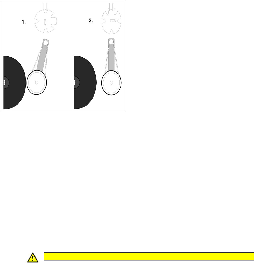
Detailed rotation of DP station, 3. Swivel out
▪ The command to start swiveling out is the end posi-
tion signal from DP positioning.
▪ The DP drive is still located at the sleeve.
▪ Diagram 1 shows the status when swiveled in.
▪ The stepping motor is controlled by the light barrier
on the cam disk.
▪ From its swiveled-in status, the stepping motor ro-
tates by 90° in a counterclockwise direction, to swivel
out.
▪ Diagram 2 shows the status when swiveled out.
CAUTION
Sie können diese Funktionen keinesfalls dazu nutzen um Zeit einzusparen. Ihre
Bestücksicherheit leidet, Bauelemente werden u. U. wieder mit hochgerissen.

9 C&P Placement Heads
9.2.13 BE-Presence 9.2 Placement Procedure
Student Guide SIPLACE D-Series (FSE) 161
Air blast control for placing back (not rejecting) with the C&P6/12 head
▪ (4) Entry and description as in (1)
▪ (5) Entry and description as in (2)
▪ (6) Entering "151-255" means: air blast valve will be switched off at a 180° rotation of the stepping
motor.
9.2.13
9.2.13 BE-Presence
BE-Presence
Im Ablauf einer Bestücksequenz des C&P12 wird geprüft ob das Vakuumsystem in Ordnung ist bzw. es
wird geprüft ob das BE korrekt an der Pipette vorhanden ist.
9.2.13.1
9.2.13.1 Component Sensor Functional Description
Component Sensor Functional Description
The component sensor for the C&P12 head functions according to the shadow casting principle, to de-
termine the height of the component on the nozzle. This means that the nozzle shadow is compared to
the shadow caused by the nozzle with component.
Measurement is performed "on the fly", during star rotation.
Conditions for measurement:
▪ The component sensor is fitted.
▪ The component sensor is configured in SIPLACE Pro and SITEST.
▪ The nozzle is longer than 12 mm and casts a shadow in the sensor.
▪ The component on the nozzle is still within the 5mm measuring range
(nozzle length in sensor + component height < 5 mm).
▪ The component has been selected for measurement in the component sensor (in order to measure
either the component presence or component height).
Component presence check modes (SIPLACE Pro programming)
Measurement procedure:
▪ Compare the "length of empty nozzle before pickup" with the "nozzle length during reference run".
▪ Compare the component on the nozzle before placement (depends on operating mode) with the
"length of the empty nozzle before pickup".
▪ After 350 head cycles, the "nozzle length during reference run" is measured again.
NOTICE! The BE sensor C&P12-Head does not measure 0,4x0,2 mm (01005).. The empty
nozzle is scanner measured before and after placement in this way the component placement is ensured
SIPLACE Pro Station software Measurement result
Advanced BE-Sensor Anwesenheitsprüfung nur vor
dem Bestücken und nur beim C&P12
und Vakuummessung nach Abholen
> nozzle length + component height - com-
ponent height tolerance
No vacuum BE-Sensor Anwesenheitsprüfung beim
C&P12 nur vor dem Bestücken.
(Beim C&P12 ohne BE-Sensor und beim
C&P6 keinerlei BE-
Anwesenheitsprüfung.)
Component
height (com-
ponent thick-
ness)
BE-Sensor Höhenmessung bei C&P12
nur vor dem Bestücken
> nozzle length + component height - com-
ponent height tolerance
and
< nozzle length + component height + com-
ponent height tolerance