00195440-05-SG_D-Series_FSE-EN.pdf - 第168页
9 C&P Placement Heads 9.4 Travel Profiles - Placement 9.4.1 Z Axis Down 168 Student Guide SIPLACE D-Series (FSE) 9.4 9 . 4 T r a v e l P r o f ile s - P la c e m e n t Travel Profiles - Placement 9.4.1 9 . 4 . 1 Z A …

9 C&P Placement Heads
9.3.2 Z Axis Up 9.3 Travel Profile - Pickup
Student Guide SIPLACE D-Series (FSE) 167
9.3.2.3
9.3.2.3 Benefits of the Special Mode "Slow Speed Upwards" and "Creep Speed Start"
Benefits of the Special Mode "Slow Speed Upwards" and "Creep Speed Start"
The function change "slow speed" (reduced speed SR/MC 407) offers the following benefits:
▪ Increases the pickup reliability for all nozzle types and for heavy/exotic COs. During the slow start,
the vacuum has the chance to develop its full holding force. An exotic component and /or a heavy
component will therefore remain safely on the nozzle!
▪ There is no danger of head contamination for nozzle types with large openings.
▪ However, this option makes the pickup procedure around 20 ms longer than the standard pickup pro-
cedure.
▪ Irrespective of the special modes, the acceleration values in the nozzle handling from SW version
503 onwards can be reduced further if required.
▪ You can also specify the Z-axis down waiting period if you are using special feeder constructions.
CAUTION
The mode "creep speed start" does not usually provide any additional benefits (except in the
case of pickup from surftape) but does reduce the placement performance considerably.
Legend
1. End position signal for X-axis
2. End position signal for star axis
3. Uncommutated current for Z drive
4. End position signal for component pickup with early
vacuum and standard acceleration up
5. End position signal for component pickup with early
vacuum and slow start up
Legend
1. End position signal for X-axis
2. End position signal for star axis
3. Uncommutated current for Z drive
4. End position signal for component pickup with early
vacuum and creep start up
5. End position signal for component pickup with early
vacuum and standard acceleration up
9 C&P Placement Heads
9.4 Travel Profiles - Placement 9.4.1 Z Axis Down
168 Student Guide SIPLACE D-Series (FSE)
9.4
9.4 Travel Profiles - Placement
Travel Profiles - Placement
9.4.1
9.4.1 Z Axis Down
Z Axis Down
9.4.1.1
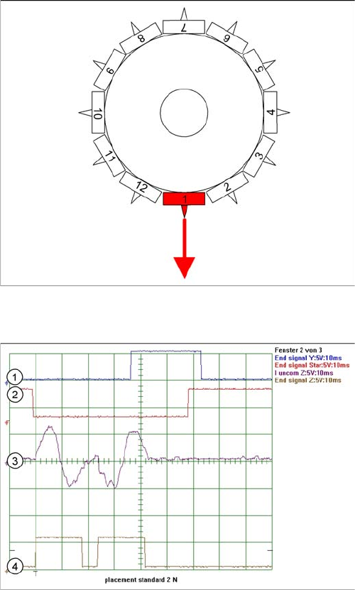
9.4.1.1 Standard Mode - Placement: Z-Axis Down
Standard Mode - Placement: Z-Axis Down
Detailed component placement procedure: Z-axis down
The placement force is roughly 2.4 N in this operating
mode, with light barrier down on the C&P12.
End position signal for X/Y and star axes:
▪ All 3 end position signals available
▪ Perform vacuum test "before placement". This deter-
mines whether the component is at the nozzle.
Z-axis starts:
▪ Positioning of Z-axis downwards
LB up switches:
▪ Electromagnetic valve for air blast ON
▪ Release signal for function LB down
LB down switches:
▪ End position signal for positioning Z-axis down;
▪ And valve positioning drive pickup/placement posi-
tion ON for air blast
Legend
1. End position signal for Y-axis (position to next place-
ment position)
2. End position signal for star axis
3. Uncommutated motor current for Z-axis
4. End position signal for Z-axis
9 C&P Placement Heads
9.4.1 Z Axis Down 9.4 Travel Profiles - Placement
Student Guide SIPLACE D-Series (FSE) 169
9.4.1.2
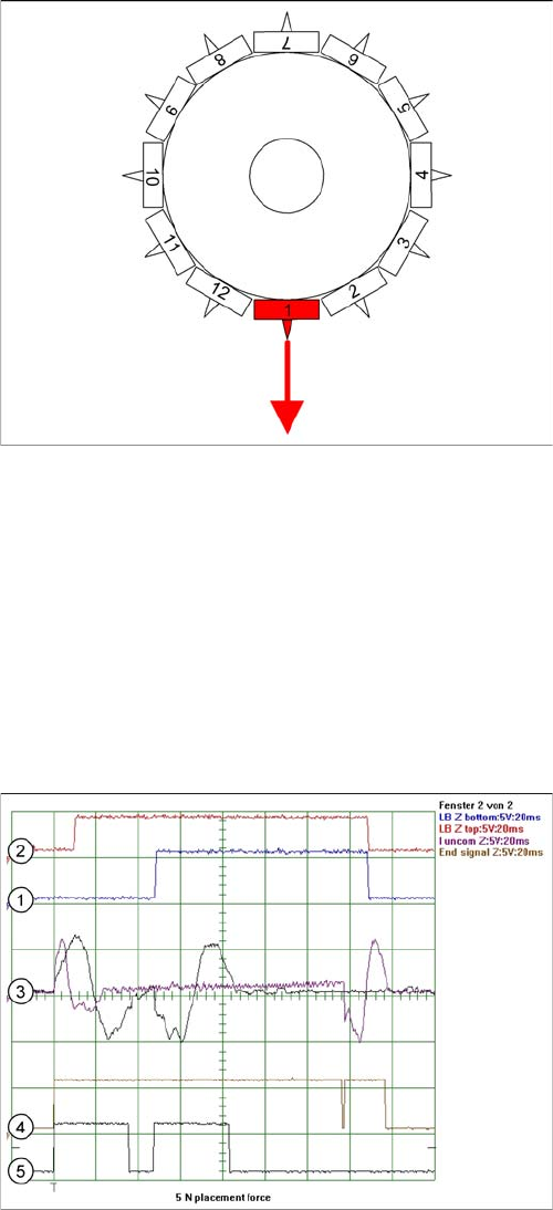
9.4.1.2 Placing with Increased Placement Force: Z-Axis Down
Placing with Increased Placement Force: Z-Axis Down
Benefits of Operating Mode "Increased Placement Force"
With this "higher placement force" function, you can:
▪ Reliably set large components and components with large contact surfaces into the soldering paste/
adhesive!
▪ However, this option makes the placement procedure around 10 ms longer than the standard place-
ment procedure!
Detailed component placement procedure: Z-axis down
The placement force is 3 -5 N in this operating mode, with
current sensor.
End position signal for X/Y and star axes:
▪ All 3 end position signals available
▪ Perform vacuum test "before placement", to deter-
mine whether the component is at the nozzle.
Z-axis starts:
▪ Positioning of Z-axis downwards
LB up switches:
▪ Electromagnetic valve for air blast ON
▪ Release signal for function LB down
LB down switches:
▪ And valve positioning drive pickup/placement posi-
tion ON for air blast
Current sensor triggers in the servo amplifier:
▪ End position signal for positioning Z-axis down;
Legend
1. Light barrier bottom position Z-axis
2. Light barrier, Z-axis up
3. Uncommutated motor currents for Z-axis (2 modes)
4. End position signal for high placement force 5 N
5. End position signal for standard placement force 2 N