00195440-05-SG_D-Series_FSE-EN.pdf - 第170页
9 C&P Placement Heads 9.4 Travel Profiles - Placement 9.4.1 Z Axis Down 170 Student Guide SIPLACE D-Series (FSE) 9.4.1.3 9 . 4 . 1 . 3 P la c e m e n t : Z A x is U p w a r d s " C r e e p t o T a r g e t P o s …
9 C&P Placement Heads
9.4.1 Z Axis Down 9.4 Travel Profiles - Placement
Student Guide SIPLACE D-Series (FSE) 169
9.4.1.2
9.4.1.2 Placing with Increased Placement Force: Z-Axis Down
Placing with Increased Placement Force: Z-Axis Down
Benefits of Operating Mode "Increased Placement Force"
With this "higher placement force" function, you can:
▪ Reliably set large components and components with large contact surfaces into the soldering paste/
adhesive!
▪ However, this option makes the placement procedure around 10 ms longer than the standard place-
ment procedure!
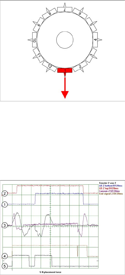
Detailed component placement procedure: Z-axis down
The placement force is 3 -5 N in this operating mode, with
current sensor.
End position signal for X/Y and star axes:
▪ All 3 end position signals available
▪ Perform vacuum test "before placement", to deter-
mine whether the component is at the nozzle.
Z-axis starts:
▪ Positioning of Z-axis downwards
LB up switches:
▪ Electromagnetic valve for air blast ON
▪ Release signal for function LB down
LB down switches:
▪ And valve positioning drive pickup/placement posi-
tion ON for air blast
Current sensor triggers in the servo amplifier:
▪ End position signal for positioning Z-axis down;
Legend
1. Light barrier bottom position Z-axis
2. Light barrier, Z-axis up
3. Uncommutated motor currents for Z-axis (2 modes)
4. End position signal for high placement force 5 N
5. End position signal for standard placement force 2 N
9 C&P Placement Heads
9.4 Travel Profiles - Placement 9.4.1 Z Axis Down
170 Student Guide SIPLACE D-Series (FSE)
9.4.1.3
9.4.1.3 Placement: Z Axis Upwards "Creep to Target Position"
Placement: Z Axis Upwards "Creep to Target Position"
Benefits of the Special Mode "Creep to Target Position"
The "slow approach to placement height" option allows you to:
▪ FLIP-CHIP components with their ball-type leads can be dipped into the filler material on the board
without trapping any air!
▪ However, this option makes the placement procedure around 20 ms longer than the standard place-
ment procedure!
9.4.1.4
9.4.1.4 Detailed Placement Procedure: Z-Axis Downwards with Waiting Time at Placement
Detailed Placement Procedure: Z-Axis Downwards with Waiting Time at Placement
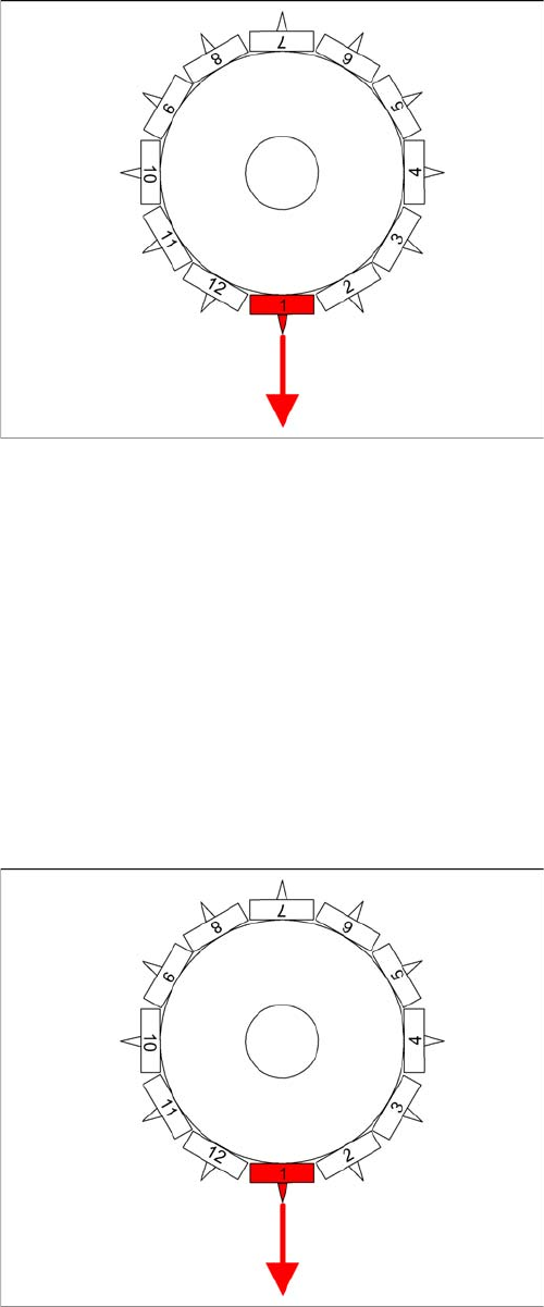
Detailed component placement procedure: Z axis up
-
wards with slow approach to placement height
In the case of LRU/LRL 503 and SIPLACE Pro, this
placement type can "only" be programmed in the CS "for
SR/MC 503 stations and higher".
End position signal for X/Y and star axes:
▪ All 3 end position signals available
▪ Perform vacuum test "before placement", to deter-
mine whether the component is at the nozzle.
Z axis starts:
▪ Positioning of Z axis downwards, the selected speed
profile switches over to minimum speed 1 mm before
reaching the placement height.
LB up switches:
▪ Electromagnetic valve for air blast ON
▪ Enable signal for "light barrier down" function
LB down switches:
▪ End signal Z axis positioning downwards;
And valve positioning drive pickup/placement position
ON for air blast
Detailed component placement procedure: Z-Axis down
-
wards with waiting time at placement
End position signal for X/Y and star axes:
▪ All 3 end position signals available
▪ Perform vacuum test "before placement", to deter-
mine whether the component is at the nozzle.
Z-axis starts:
▪ Positioning of Z-axis downwards
LB up switches:
▪ Electromagnetic valve for air blast ON
▪ Release signal for function LB down
LB down switches:
▪ End position signal for positioning Z-axis down;
▪ And valve positioning drive pickup/placement posi-
tion ON for air blast
Special mode "Waiting time down"
▪ The end position signal Z-axis down starts the waiting
period timer in the MC.
▪ After the waiting period, the air blast pressure is
measured.
▪ Positioning upwards begins.
9 C&P Placement Heads
9.4.2 Z Axis Up 9.4 Travel Profiles - Placement
Student Guide SIPLACE D-Series (FSE) 171
Benefits of special mode "waiting time - placement"
With the "waiting time - placement" option you can:
▪ Combine any of the Z-axis operating modes.
With this "waiting time - placement" option you can:
▪ Press the BARE-DIE component into the adhesive with placement force, so that the adhesive flows
under the component surface and sticks over the surface.
▪ Very big COs can be pressed into the soldering paste so that all leads contact with the paste.
9.4.2
9.4.2 Z Axis Up
Z Axis Up
9.4.2.1
9.4.2.1 Standard Mode - Placement: Z-Axis Up
Standard Mode - Placement: Z-Axis Up
CAUTION
The Z-axis moves up (SW 6xx) if the emergency stop button is pressed or a protective cover is
opened!
NOTICE
The pickup process offers the same programming options for a waiting period at the bottom (for
pickup from surftape feeders (typical: 250 ms)). However, due to the waiting period, this option
makes the placement procedure longer than the standard placement procedure!
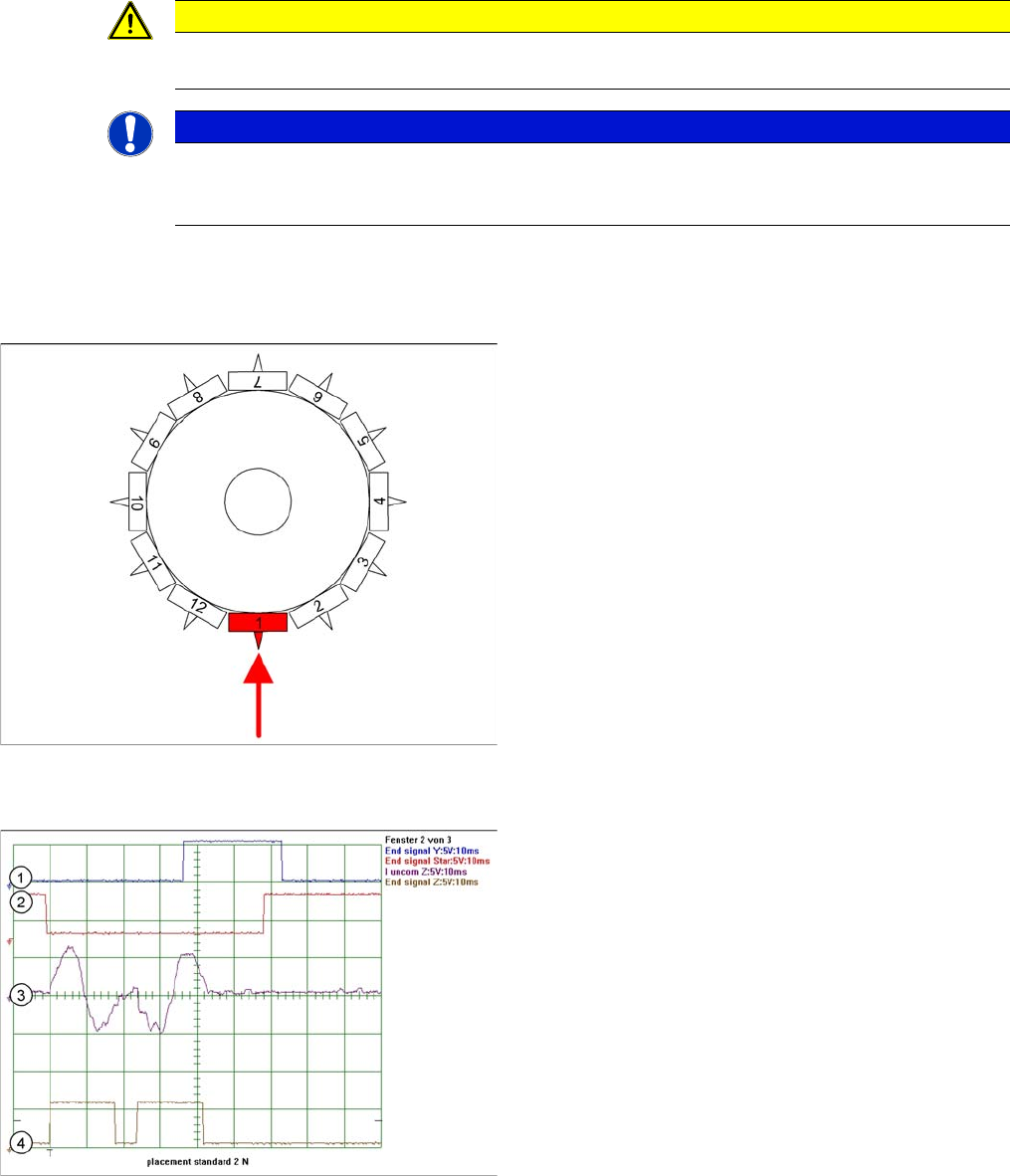
Detailed component placement procedure: Z-axis up
LB down switches:
▪ End position signal for downwards and valve posi-
tioning drive "ON" for air blast
▪ Measurement of air blast pressure during placement
▪ Start signal for upwards movement
Z-axis starts:
▪ Positioning of Z-axis upwards
LB up switches:
▪ Electromagnetic valve for air blast OFF
▪ Reset LB down signal
▪ Start signal for gantry axes
Z-axis end position signal (Z-axis at 0 position):
▪ Enables vacuum query: "Segment airtight" after
placement (SR/MC503)
▪ Start signal for star axis
Legend
1. End position signal for Y-axis (position to next place-
ment position)
2. End position signal for star axis
3. Uncommutated motor current for Z-axis
4. End signal Z-Axix – Teh secondsignal is displayed
with a time delay of ca. 25 ms