00195440-05-SG_D-Series_FSE-EN.pdf - 第172页
9 C&P Placement Heads 9.5 Settings 9.5.1 Boards at C&P12 172 Student Guide SIPLACE D-Series (FSE) 9.4.2.2 9 . 4 . 2 . 2 P la c e m e n t : Z - A x is U p w a r d s w it h " S lo w S t a r t " Placement:…
9 C&P Placement Heads
9.4.2 Z Axis Up 9.4 Travel Profiles - Placement
Student Guide SIPLACE D-Series (FSE) 171
Benefits of special mode "waiting time - placement"
With the "waiting time - placement" option you can:
▪ Combine any of the Z-axis operating modes.
With this "waiting time - placement" option you can:
▪ Press the BARE-DIE component into the adhesive with placement force, so that the adhesive flows
under the component surface and sticks over the surface.
▪ Very big COs can be pressed into the soldering paste so that all leads contact with the paste.
9.4.2
9.4.2 Z Axis Up
Z Axis Up
9.4.2.1
9.4.2.1 Standard Mode - Placement: Z-Axis Up
Standard Mode - Placement: Z-Axis Up
CAUTION
The Z-axis moves up (SW 6xx) if the emergency stop button is pressed or a protective cover is
opened!
NOTICE
The pickup process offers the same programming options for a waiting period at the bottom (for
pickup from surftape feeders (typical: 250 ms)). However, due to the waiting period, this option
makes the placement procedure longer than the standard placement procedure!
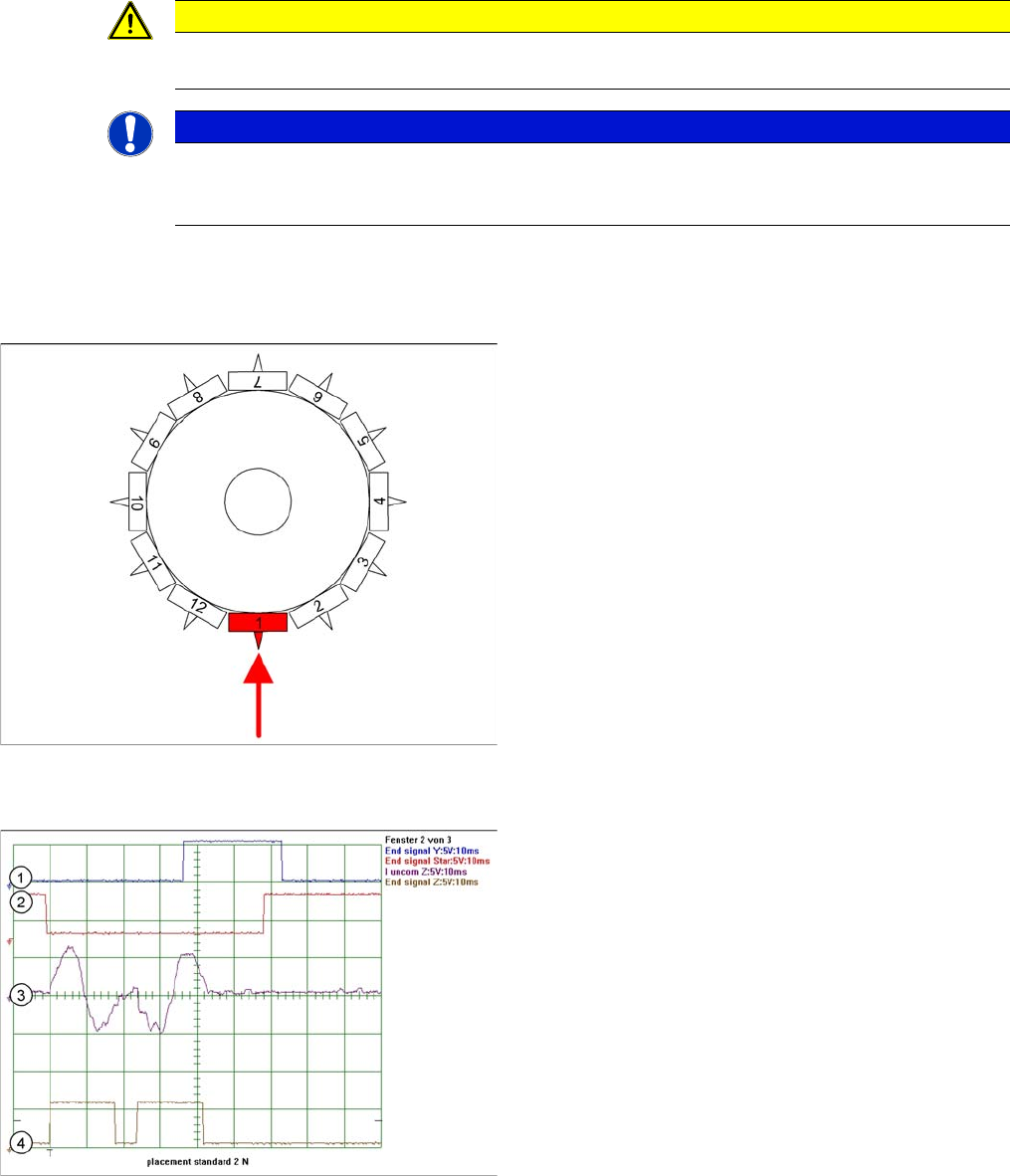
Detailed component placement procedure: Z-axis up
LB down switches:
▪ End position signal for downwards and valve posi-
tioning drive "ON" for air blast
▪ Measurement of air blast pressure during placement
▪ Start signal for upwards movement
Z-axis starts:
▪ Positioning of Z-axis upwards
LB up switches:
▪ Electromagnetic valve for air blast OFF
▪ Reset LB down signal
▪ Start signal for gantry axes
Z-axis end position signal (Z-axis at 0 position):
▪ Enables vacuum query: "Segment airtight" after
placement (SR/MC503)
▪ Start signal for star axis
Legend
1. End position signal for Y-axis (position to next place-
ment position)
2. End position signal for star axis
3. Uncommutated motor current for Z-axis
4. End signal Z-Axix – Teh secondsignal is displayed
with a time delay of ca. 25 ms
9 C&P Placement Heads
9.5 Settings 9.5.1 Boards at C&P12
172 Student Guide SIPLACE D-Series (FSE)
9.4.2.2
9.4.2.2 Placement: Z-Axis Upwards with "Slow Start"
Placement: Z-Axis Upwards with "Slow Start"
Benefits of Special Mode "Slow Start"
▪ Das BE bleibt sicher auf der LP liegen, auch wenn die Haftkräfte der Lotpaste sehr gering sind.
9.5
9.5 Settings
Settings
9.5.1
9.5.1 Boards at C&P12
Boards at C&P12
All the settings described in this chapter are head-specific and apply here for the C&P12.
9.5.1.1
9.5.1.1 8-fold DIP Switch of the gantry head distributor (incl. switch S1) – C&P6/12
8-fold DIP Switch of the gantry head distributor (incl. switch S1) – C&P6/12
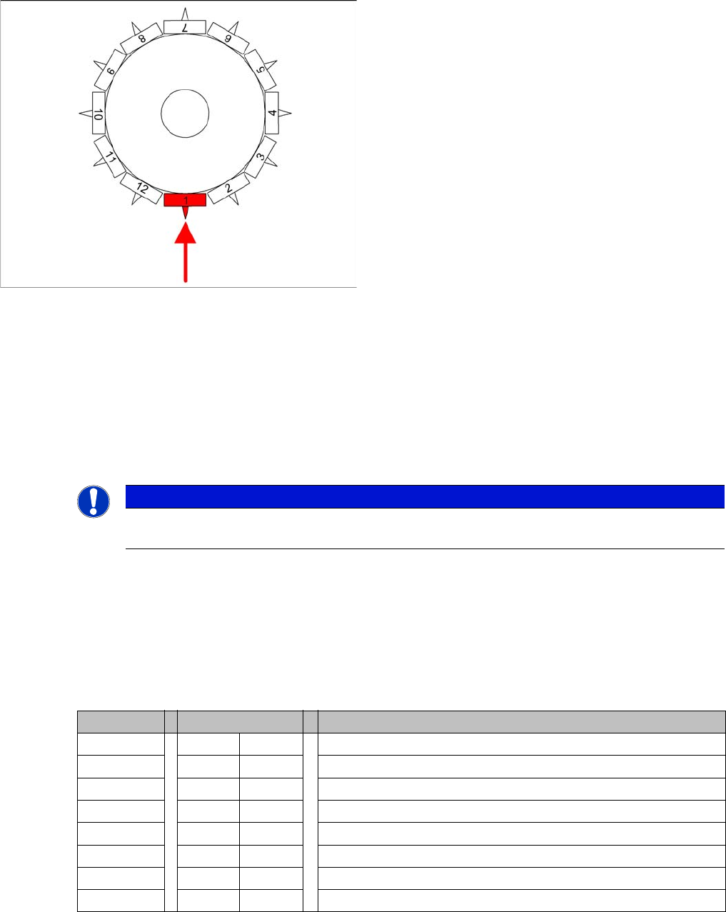
Detailed component placement procedure: Z-axis up
-
wards with slow start from placed component
From LRU/LRL 503 and SIPLACE Pro, this placement
type can "only" be programmed in the CS "for SR/MC 503
stations and higher".
LB down switches:
▪ End position signal for downwards and valve posi-
tioning drive ON for air blast
▪ Measurement of air blast pressure during placement
▪ Start signal for upwards movement
Z-axis starts:
▪ Positioning Z-axis up with reduced starting speed for
the first 44 digits
LB up switches:
▪ Electromagnetic valve for air blast OFF
▪ Reset LB down signal
▪ Start signal for gantry axes
Z-axis end position signal (Z-axis at 0 position):
▪ Enables vacuum query: "segment airtight?" after
placement (SR/MC503)
▪ Start signal for star axis
NOTICE
However, this option makes the placement procedure around 20 ms longer than the standard
placement procedure.
DIP switch Switch position Designation
1 OFF P0 (see below)
2 OFF P1 (see below)
3 OFF "S1" for test mode (see below)
4 OFF BL – Enable boot loader for serial port
5 OFF Res (Reset) – CAN processor 16 bit (TQ module)
6 OFF C0 – no current function
7 OFF C1 – no current function
8 OFF S2 – switch for DLM head (no current function)

9 C&P Placement Heads
9.5.1 Boards at C&P12 9.5 Settings
Student Guide SIPLACE D-Series (FSE) 173
Switch P0 and P1:
Gantry selection via switch P0 and P1
Switch S1:
▪ ON – Test mode (without delay)
▪ OFF – Default state (with delay of 3.6 ms+/- 300 us) means: Z axis moves downwards, the top LB is
released and the LB down is enabled after a delay of 3.6 ms.
See also
9.5.1.2 Description of LEDs on the Gantry Head Distributor [ ➙ 174]
S Gantry 1 Gantry 2 Gantry 3 Gantry 4 Designation
1 OFF ON OFF ON P0
2 OFF OFF ON ON G1