00195440-05-SG_D-Series_FSE-EN.pdf - 第173页
9 C&P Placement Heads 9.5.1 Boards at C&P12 9.5 Settings Student Guide SIPLACE D-Series (FSE) 173 Switch P0 and P1: Gantry selec tion via switch P0 and P1 Switch S1: ▪ ON – Test mode (without delay) ▪ OFF – Defau…
9 C&P Placement Heads
9.5 Settings 9.5.1 Boards at C&P12
172 Student Guide SIPLACE D-Series (FSE)
9.4.2.2
9.4.2.2 Placement: Z-Axis Upwards with "Slow Start"
Placement: Z-Axis Upwards with "Slow Start"
Benefits of Special Mode "Slow Start"
▪ Das BE bleibt sicher auf der LP liegen, auch wenn die Haftkräfte der Lotpaste sehr gering sind.
9.5
9.5 Settings
Settings
9.5.1
9.5.1 Boards at C&P12
Boards at C&P12
All the settings described in this chapter are head-specific and apply here for the C&P12.
9.5.1.1
9.5.1.1 8-fold DIP Switch of the gantry head distributor (incl. switch S1) – C&P6/12
8-fold DIP Switch of the gantry head distributor (incl. switch S1) – C&P6/12
Detailed component placement procedure: Z-axis up
-
wards with slow start from placed component
From LRU/LRL 503 and SIPLACE Pro, this placement
type can "only" be programmed in the CS "for SR/MC 503
stations and higher".
LB down switches:
▪ End position signal for downwards and valve posi-
tioning drive ON for air blast
▪ Measurement of air blast pressure during placement
▪ Start signal for upwards movement
Z-axis starts:
▪ Positioning Z-axis up with reduced starting speed for
the first 44 digits
LB up switches:
▪ Electromagnetic valve for air blast OFF
▪ Reset LB down signal
▪ Start signal for gantry axes
Z-axis end position signal (Z-axis at 0 position):
▪ Enables vacuum query: "segment airtight?" after
placement (SR/MC503)
▪ Start signal for star axis
NOTICE
However, this option makes the placement procedure around 20 ms longer than the standard
placement procedure.
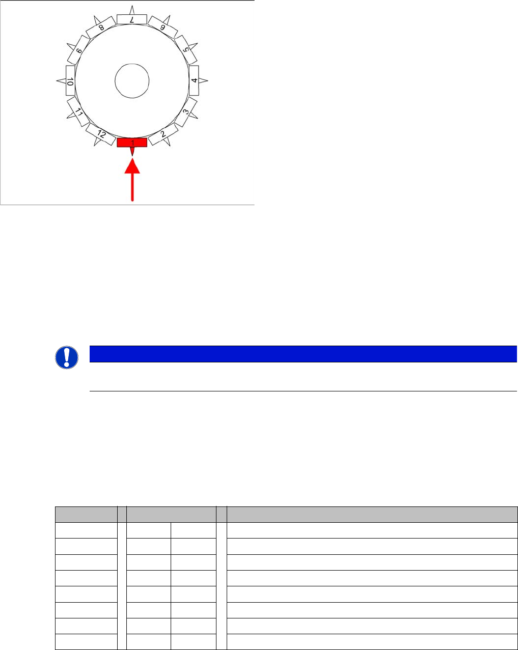
DIP switch Switch position Designation
1 OFF P0 (see below)
2 OFF P1 (see below)
3 OFF "S1" for test mode (see below)
4 OFF BL – Enable boot loader for serial port
5 OFF Res (Reset) – CAN processor 16 bit (TQ module)
6 OFF C0 – no current function
7 OFF C1 – no current function
8 OFF S2 – switch for DLM head (no current function)

9 C&P Placement Heads
9.5.1 Boards at C&P12 9.5 Settings
Student Guide SIPLACE D-Series (FSE) 173
Switch P0 and P1:
Gantry selection via switch P0 and P1
Switch S1:
▪ ON – Test mode (without delay)
▪ OFF – Default state (with delay of 3.6 ms+/- 300 us) means: Z axis moves downwards, the top LB is
released and the LB down is enabled after a delay of 3.6 ms.
See also
9.5.1.2 Description of LEDs on the Gantry Head Distributor [ ➙ 174]
S Gantry 1 Gantry 2 Gantry 3 Gantry 4 Designation
1 OFF ON OFF ON P0
2 OFF OFF ON ON G1
9 C&P Placement Heads
9.5 Settings 9.5.1 Boards at C&P12
174 Student Guide SIPLACE D-Series (FSE)
9.5.1.2
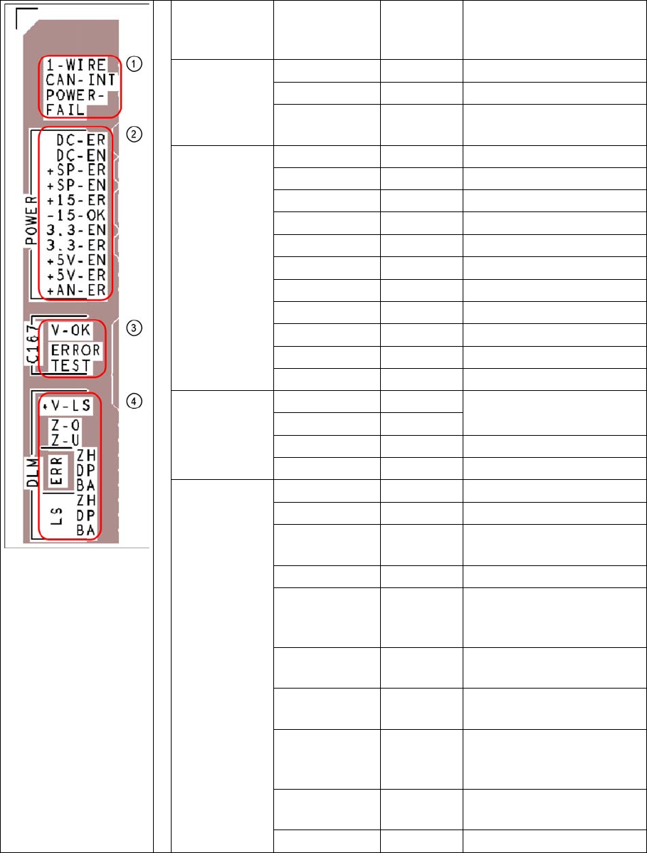
9.5.1.2 Description of LEDs on the Gantry Head Distributor
Description of LEDs on the Gantry Head Distributor
SM = stepping motor
Legend PCB labeling LEDS for
oeprating
states
Description
1
CAN Bus
1-WIRE Not in use
CAN-INT OFF not used
POWER-FAIL OFF Error +24 V power supply
(from the main machine)
2
Status voltage
supplies
DC-ER OFF Error DC/DC converter
DC-EN ON Enable DC/DC converter
+SP-ER OFF Error +5V track encoder
+SP-EN ON Enable +5V track encoder
+15-ER OFF Error +15V
-15-OK ON -15V is OK
3.3-EN ON Enable +3.3V digital
3.3-ER OFF Error +3.3V digital
+5V-EN ON Enable +5 V digital
+5V-ER OFF Error +5V digital
+AN-ER OFF Error analog supply C167
3
Head CAN
processor
V-OK ON Internal voltage monitoring
of eSW
V-OK OFF
ERROR OFF Error eSW
TEST Flashing Timer eSW in operation
4
C&P head
functions and
signals
+V-LS ON OK + 15V light barrier
+V-LS OFF Error +15V light barrier
Z-O ON Z axis is not up (in fork light
barrier)
Z-U ON Z down has switched
ERR-ZH OFF Overload SM valve position-
ing drive for pickup and
place
ERR-DP OFF Overload SM swivel in DP
axis
ERR-BA OFF Overload SM valve position-
ing drive for reject
LS-ZH ON Light barrier SM valve posi-
tioning drive for pickup and
place
LS-DP ON Light barrier SM for swivel in
DP axis
LS-BA ON Light barrier SM reject