00195440-05-SG_D-Series_FSE-EN.pdf - 第175页
9 C&P Placement Heads 9.5.1 Boards at C&P12 9.5 Settings Student Guide SIPLACE D-Series (FSE) 175 9.5.1.3 9 . 5 . 1 . 3 V is io n B o a r d ( D ig it a l) Vision Board (Digital) The Vision pr ocessor boa rd is mo…
9 C&P Placement Heads
9.5 Settings 9.5.1 Boards at C&P12
174 Student Guide SIPLACE D-Series (FSE)
9.5.1.2
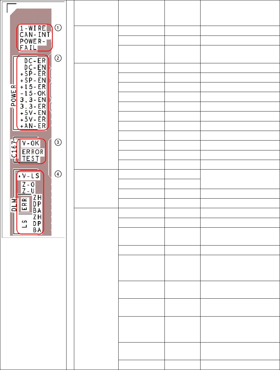
9.5.1.2 Description of LEDs on the Gantry Head Distributor
Description of LEDs on the Gantry Head Distributor
SM = stepping motor
Legend PCB labeling LEDS for
oeprating
states
Description
1
CAN Bus
1-WIRE Not in use
CAN-INT OFF not used
POWER-FAIL OFF Error +24 V power supply
(from the main machine)
2
Status voltage
supplies
DC-ER OFF Error DC/DC converter
DC-EN ON Enable DC/DC converter
+SP-ER OFF Error +5V track encoder
+SP-EN ON Enable +5V track encoder
+15-ER OFF Error +15V
-15-OK ON -15V is OK
3.3-EN ON Enable +3.3V digital
3.3-ER OFF Error +3.3V digital
+5V-EN ON Enable +5 V digital
+5V-ER OFF Error +5V digital
+AN-ER OFF Error analog supply C167
3
Head CAN
processor
V-OK ON Internal voltage monitoring
of eSW
V-OK OFF
ERROR OFF Error eSW
TEST Flashing Timer eSW in operation
4
C&P head
functions and
signals
+V-LS ON OK + 15V light barrier
+V-LS OFF Error +15V light barrier
Z-O ON Z axis is not up (in fork light
barrier)
Z-U ON Z down has switched
ERR-ZH OFF Overload SM valve position-
ing drive for pickup and
place
ERR-DP OFF Overload SM swivel in DP
axis
ERR-BA OFF Overload SM valve position-
ing drive for reject
LS-ZH ON Light barrier SM valve posi-
tioning drive for pickup and
place
LS-DP ON Light barrier SM for swivel in
DP axis
LS-BA ON Light barrier SM reject
9 C&P Placement Heads
9.5.1 Boards at C&P12 9.5 Settings
Student Guide SIPLACE D-Series (FSE) 175
9.5.1.3
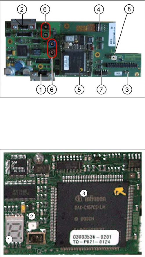
9.5.1.3 Vision Board (Digital)
Vision Board (Digital)
The Vision processor board is mounted on the gantry head distributor board. This PCB is used for all
four gantries.
9.5.1.4
9.5.1.4 CAN 16 bit processor board (TQ module)
CAN 16 bit processor board (TQ module)
Description of 7-segment display (normal operation "." flashes):
▪ After switch ON the machine appears " 0 " on the display
▪ Display "b" --> BIOS was started.
▪ Display flashes alternatively between "b" and "." --> no application available or unable to start appli-
cation.
▪ Display " -I " and " I- " application was loaded.
▪ "." flashes on the display --> ready for operation.
Vision board
Legend
1. X8 Connector illumination and video signals PCB
camera
2. X3 Connector illumination and video signals compo-
nent camera
3. LEDs P15V - 15Volt / Vcc - Power supply Vision
board
4. DIP switch
5. CAN processor 16 bit (TQM module)
6. Connector X22 - X25 - Connectors for the video cable
to the trailing cable
7. Connector X11 for download
8. Voltage supply 11 VDC, measurable
16 bit processor (TQ module)
Legend
1. 7 Segment display
2. LED for manual RESET of processor
3. 16 bit processor
The 16 BIT CAN processor is used for various different
functions in the following units:
(see chapter communication and control too)
▪ Visionboard, communication and control via the CAN
Bus to the Vision computer.
▪ Gantry head distributor, control of head processes
and vacuum
9 C&P Placement Heads
9.5 Settings 9.5.1 Boards at C&P12
176 Student Guide SIPLACE D-Series (FSE)
9.5.1.5
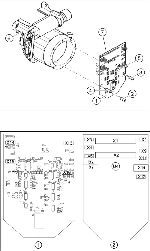
9.5.1.5 SP_12 Digital Intermediate Distributor [00330648-05]
SP_12 Digital Intermediate Distributor [00330648-05]
The following supply voltages and signals are routed by the intermediate distributor to the individual
placement head modules or to the head board:
Intermediate distributor
Legend
1. Intermediate distributor
2. Spacer bolt M3x10
3. Spacer bolt M3x10
4. Spacer bolt M3x10
5. Spacer bolt M3x10
6. Front section of C&P head
7. Connectors X1 and X2 (on the rear side)
The intermediate distributor (1) is fixed to the front part (6)
with four spacer bolts (items 2, 3, 4 and 5). The pressure
sensor is located above the spacer bolts (5), on the back
of the intermediate distribution board. The cover of the in-
termediate distributor is fixed with push buttons.
Position of the sockets
Legend
1. Front of the intermediate distributor
2. Back of the intermediate distributor
U4 = pressure sensor
Two 40-pin ribbon cables run from plug X1 and X2 on the
intermediate distributor to socket X14 / X13 on the head
board.