00195440-05-SG_D-Series_FSE-EN.pdf - 第182页
10 P&P and TWIN Heads 10.1 Overview 10.1.2 Overview – Twin Head in D/Di-Ser ies 182 Student Guide SIPLACE D-Series (FSE) 10.1.2 1 0 . 1 . 2 O v e r v ie w – T w in H e a d in D / D i- S e r ie s Overview – Twin H ead…
10 P&P and TWIN Heads
10.1.1 Technical Data Twin Head 10.1 Overview
Student Guide SIPLACE D-Series (FSE) 181
10
10 P&P and TWIN Heads
P&P and TWIN Heads
10.1
10.1 Overview
Overview
10.1.1
10.1.1 Technical Data Twin Head
Technical Data Twin Head
NOTICE
Cause of Hazard
The following descriptions for the D3 TWIN Head also apply correspondingly for the D1/D1i
P&P head.
The D1/D1i P&P head corresponds to one of the two D3 TWIN segments.
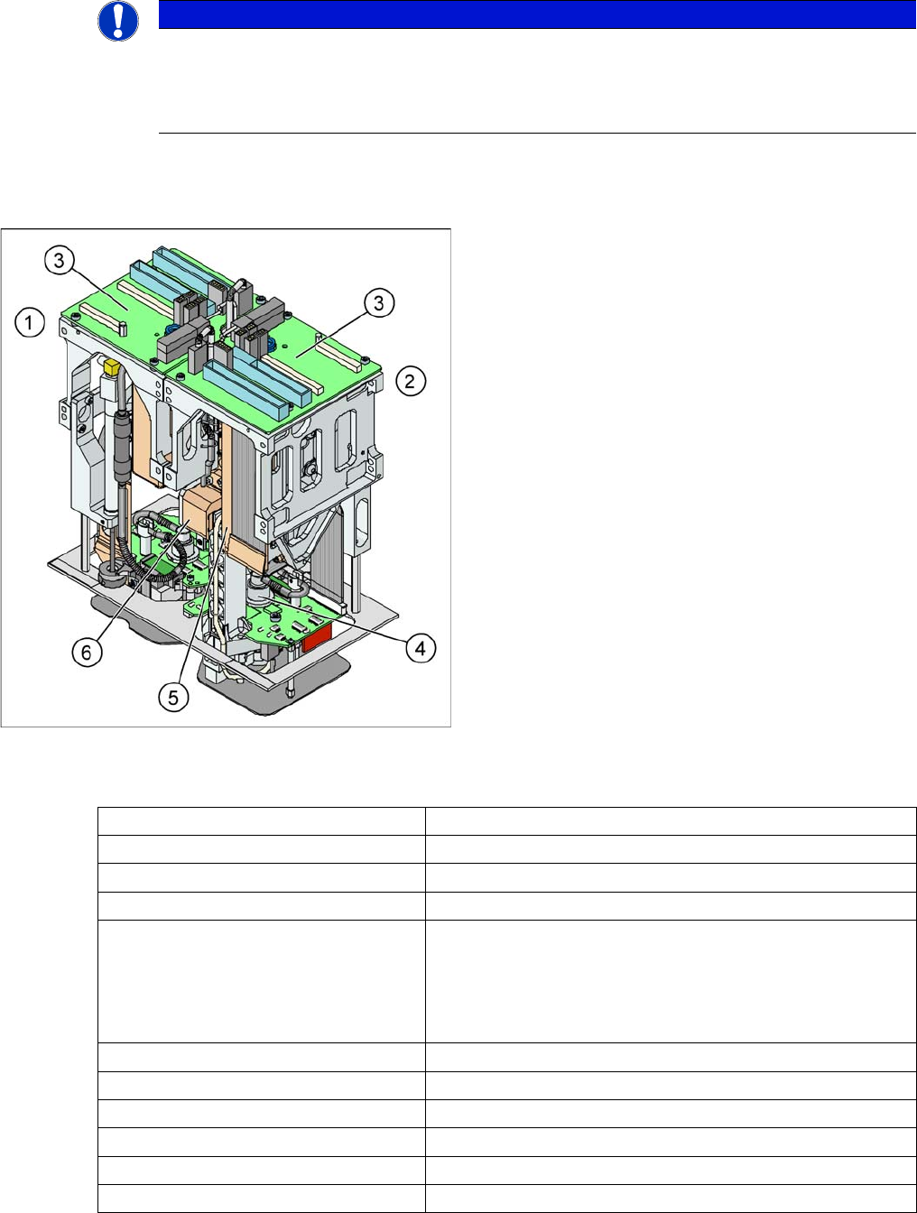
Legend
1. Module 1
2. Module 2, rotate by 180 ° compared to module 1.
3. Main board on modul 1 and modul 2
4. D Axis
5. Linear motorZ Axis
6. Z axis incremental measurement system
The Twin head consists of two identical modules which
work according to the Pick&Place principle. The second
P&P head is rotated 180 degrees.
For the Twin-head, new nozzles (Type 5xx) were devel-
oped. However, the nozzles of the Pick&Place head type
4xx and the nozzles of the Collect&Place heads type 8xx
and 9xx we can use with an adapter.
Placement accuracy (X/Y) 35µm by 4 sigma with IC camera
Placement accuracy (X/Y) 30µm by 4 sigma with FC camera
Placement accuracy (Angle) 0,07° by 4sigma
Placement speed 3500 cph
Maximum component size: 50 up to 40 mm single measurement on both segments
69 up to 10 mm (multiple measurement on both segments)
125 up to 10 mm ( multiple measurement on one segment)
200 up to 125 mm (multiple measurement with restrictions on
one segment )
Max. component height 25 mm
Placement force 1 - 15 N
D-Axis / Resolution direct drive / 0,001 degree
Z Axis / Resolution Linear motor / 0,5 µm
Travel range Z axis app. 60 mm
Nozzle types 5xx (4xx, 8xx, 9xx with adapter)
10 P&P and TWIN Heads
10.1 Overview 10.1.2 Overview – Twin Head in D/Di-Series
182 Student Guide SIPLACE D-Series (FSE)
10.1.2
10.1.2 Overview – Twin Head in D/Di-Series
Overview – Twin Head in D/Di-Series
As the name implies, 2 identical placement heads have been combined to form a single unit. The TWIN
Head in the form of these 2 segments is mounted on the D3 machine.
Hardware - new features for P&P placement head
Camera features for P&P placement head
Distance between the segments approx. 71,00 mm
Max. weight of component 100 g
Option high force Twin head placement
force
max. 30 N (only X series)
Placement head D4/D4i D3 D2/D2i D1/D1i D1/D1i single
head
Twin Head ---- Yes, complete
with 2 seg-
ments
---
P&P module. ---- Yes, equals one
TWIN segment
Yes or alterna-
tively C&P
head
High-force head ---- Option possible --- No
Controlled via ---- Processor on
head interface
--- Processor on gantry head distrib-
utor
Electrically con-
trolled vacuum
generator
---- Analog --- Analog
Version 5 with: ---- Rotary part connection via fixed pipe bracket with silicon tube
---- New Z-axis linear guide
D-axis zero point
correction
---- Mark for meas-
urement nozzle
to MA center
---- Remember that the D1/D1i only
has PA1 and that therefore the
calibration nozzle mark must
point to the output conveyor!
The two centering pins for the
nozzle pickup point towards the
back of the head!!
Camera D4/D4i
with C&P12
D3
with C&P12
D2/D2i
with C&P12
D1/D1i
with C&P12
D1/D1i fit-
ted with
P&P mod-
ule
D1/D1i
with C&P12
Standard P&P -X- --- SST33 ---
Standard P&P -D --- SST36 option SST33
FilpChip option --- SST25 --- SST25
10 P&P and TWIN Heads
10.1.3 Vacuum generator TwinHead 10.1 Overview
Student Guide SIPLACE D-Series (FSE) 183
Nozzle changer (NC) for P&P heads
Nozzle changer features for P&P placement head
10.1.3
10.1.3 Vacuum generator TwinHead
Vacuum generator TwinHead
Assembly D3 D2/D2i D1/D1i
NC types TWIN NC 12 magazines
in series X compatibility
--- TWIN NC in 2x5 magazine
arrangement
Dual magazine X compatible --- New (higher X/Y measure-
ment fiducials and eccen-
tric fixture)
Single magazine X compatible --- New (higher fiducial and
eccentric fixture)
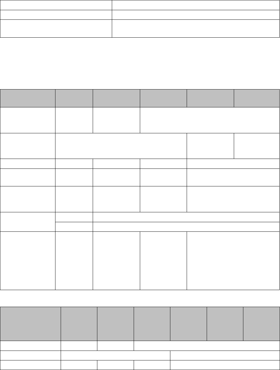
Vacuum generator
The vacuum generator automatically controls the vacu-
um, air blast and the zero balancing position (middle po-
sition-->no vacuum and no air blast) for the segments,
with the aid of an iron core and inductor.
Legend
1. Compressed air input
2. X series, D3: Cooling for X linear motor
D1/D1i: Discharged air to silencer
3. Output vacuum - vacuum is passed through the D-
axis motor shaft and then to the nozzle.
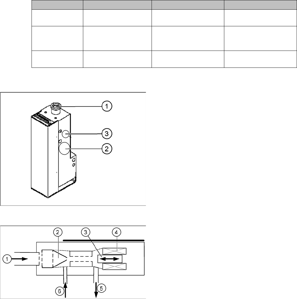
Principle of the vacuum generator
Legend
1. Compressed air input
2. Venturi nozzle
3. Plunger (iron core)
4. Plunger drive (inductor)
5. Discharged air to silencer
6. Vacuum air blast output