00195440-05-SG_D-Series_FSE-EN.pdf - 第183页
10 P&P and TWIN Heads 10.1.3 Vacuum generator TwinHead 10.1 Overview Student Guide SIPLACE D-Series (FSE) 183 Nozzle changer (NC) for P&P heads Nozzle changer features for P&P pla cement head 10.1.3 1 0 . 1 .…

10 P&P and TWIN Heads
10.1 Overview 10.1.2 Overview – Twin Head in D/Di-Series
182 Student Guide SIPLACE D-Series (FSE)
10.1.2
10.1.2 Overview – Twin Head in D/Di-Series
Overview – Twin Head in D/Di-Series
As the name implies, 2 identical placement heads have been combined to form a single unit. The TWIN
Head in the form of these 2 segments is mounted on the D3 machine.
Hardware - new features for P&P placement head
Camera features for P&P placement head
Distance between the segments approx. 71,00 mm
Max. weight of component 100 g
Option high force Twin head placement
force
max. 30 N (only X series)
Placement head D4/D4i D3 D2/D2i D1/D1i D1/D1i single
head
Twin Head ---- Yes, complete
with 2 seg-
ments
---
P&P module. ---- Yes, equals one
TWIN segment
Yes or alterna-
tively C&P
head
High-force head ---- Option possible --- No
Controlled via ---- Processor on
head interface
--- Processor on gantry head distrib-
utor
Electrically con-
trolled vacuum
generator
---- Analog --- Analog
Version 5 with: ---- Rotary part connection via fixed pipe bracket with silicon tube
---- New Z-axis linear guide
D-axis zero point
correction
---- Mark for meas-
urement nozzle
to MA center
---- Remember that the D1/D1i only
has PA1 and that therefore the
calibration nozzle mark must
point to the output conveyor!
The two centering pins for the
nozzle pickup point towards the
back of the head!!
Camera D4/D4i
with C&P12
D3
with C&P12
D2/D2i
with C&P12
D1/D1i
with C&P12
D1/D1i fit-
ted with
P&P mod-
ule
D1/D1i
with C&P12
Standard P&P -X- --- SST33 ---
Standard P&P -D --- SST36 option SST33
FilpChip option --- SST25 --- SST25
10 P&P and TWIN Heads
10.1.3 Vacuum generator TwinHead 10.1 Overview
Student Guide SIPLACE D-Series (FSE) 183
Nozzle changer (NC) for P&P heads
Nozzle changer features for P&P placement head
10.1.3
10.1.3 Vacuum generator TwinHead
Vacuum generator TwinHead
Assembly D3 D2/D2i D1/D1i
NC types TWIN NC 12 magazines
in series X compatibility
--- TWIN NC in 2x5 magazine
arrangement
Dual magazine X compatible --- New (higher X/Y measure-
ment fiducials and eccen-
tric fixture)
Single magazine X compatible --- New (higher fiducial and
eccentric fixture)
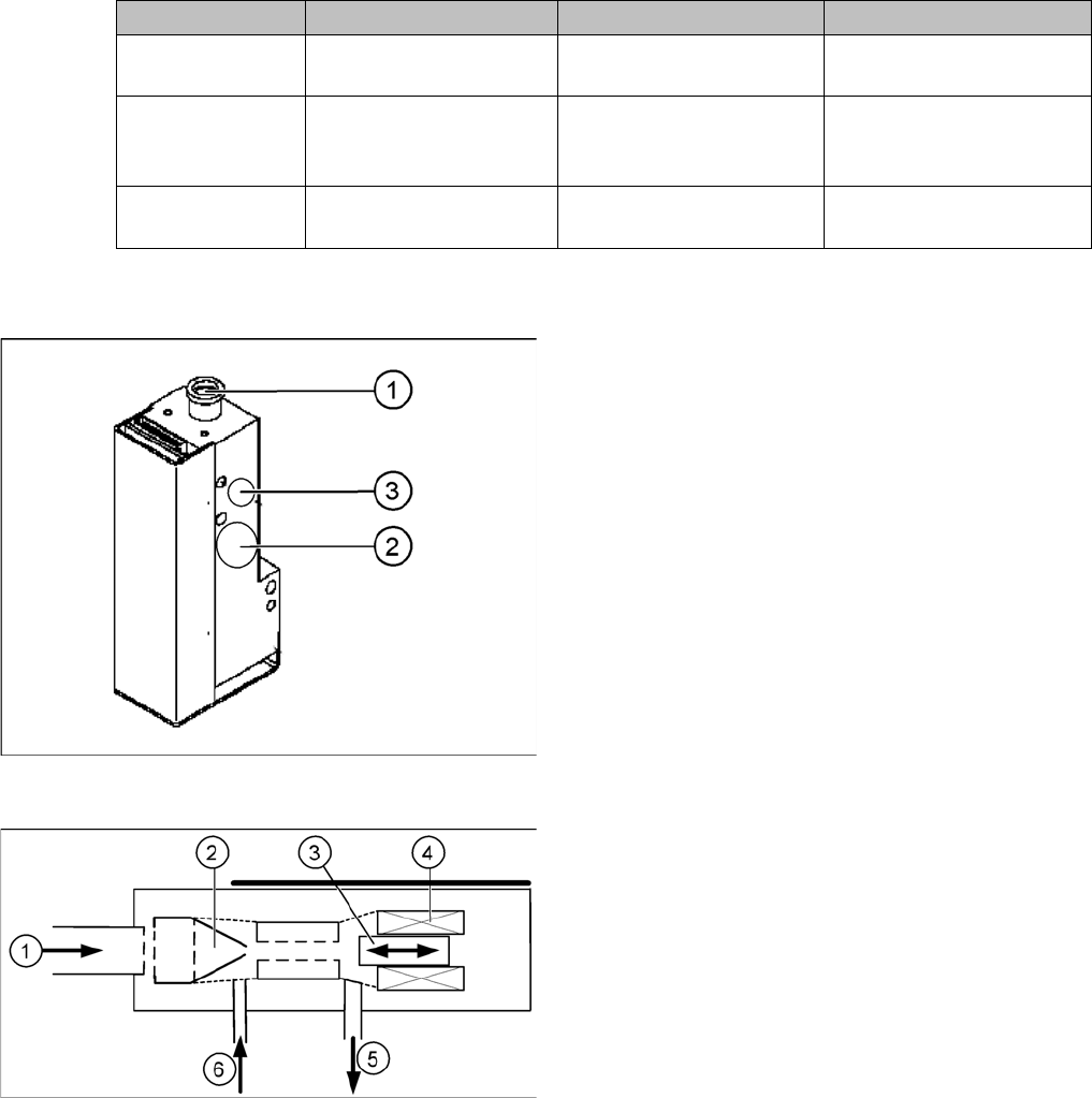
Vacuum generator
The vacuum generator automatically controls the vacu-
um, air blast and the zero balancing position (middle po-
sition-->no vacuum and no air blast) for the segments,
with the aid of an iron core and inductor.
Legend
1. Compressed air input
2. X series, D3: Cooling for X linear motor
D1/D1i: Discharged air to silencer
3. Output vacuum - vacuum is passed through the D-
axis motor shaft and then to the nozzle.
Principle of the vacuum generator
Legend
1. Compressed air input
2. Venturi nozzle
3. Plunger (iron core)
4. Plunger drive (inductor)
5. Discharged air to silencer
6. Vacuum air blast output
10 P&P and TWIN Heads
10.2 Twin Head Pickup and Place Cycle 10.2.1 Twin Head Placement Principle
184 Student Guide SIPLACE D-Series (FSE)
10.2
10.2 Twin Head Pickup and Place Cycle
Twin Head Pickup and Place Cycle
10.2.1
10.2.1 Twin Head Placement Principle
Twin Head Placement Principle
During the PCB transport time, the gantry waits at the theoretical fiducial position, to perform board cen-
tering (and inkspot recognition) after PCB clamping. With the " Whispering down the machine" option,
gantry 3 only evaluates 2 fiducials.
Than the Twin-head start to collect one component with module 1 and one component with module 2.
These components are then centered with the IC camera (FC camera) and are placed.
10.2.2
10.2.2 Preparations for Component Pickup (Module 1)
Preparations for Component Pickup (Module 1)
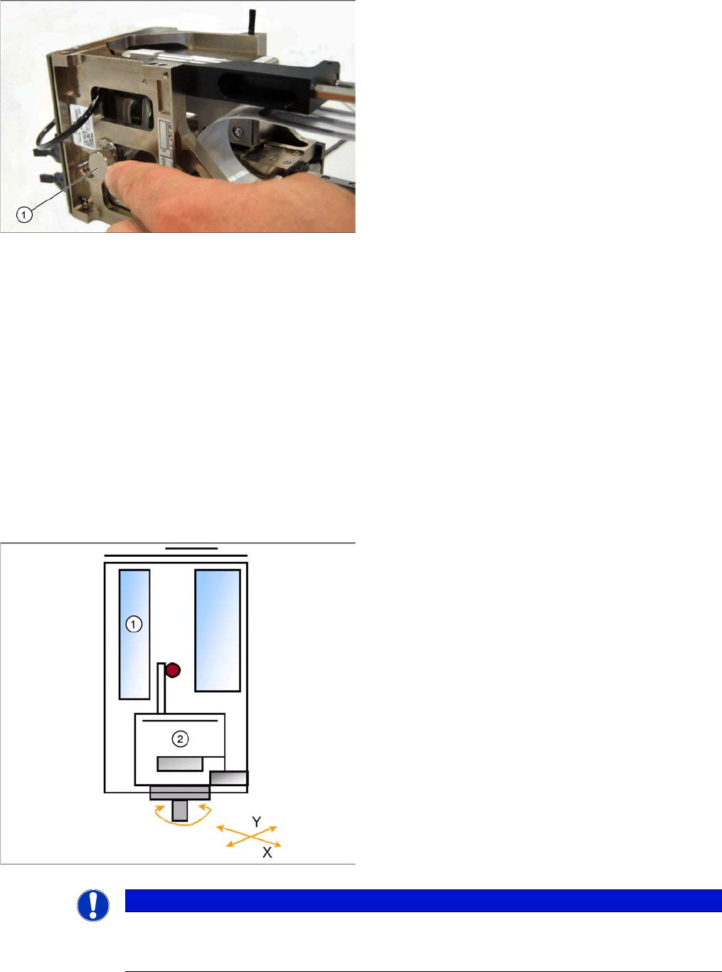
Filter for the vacuum system (example of Twin segment
version 03 shown)
Legend
1. Filter for the vacuum system on the Twin- head.
The Filter is mounted on the retract unit and used as an
attenuator to control the vacuum. The filter with the addi-
tional volume reduces the oscillation of the vacuum gen-
erator and guarantees an accurate vacuum and air blast
supply. The filter is serviced at regular intervals, which
must be adhered to (see maintenance guide).
Legend
1. Z-motor
2. D motor
▪ PCB position recognition and ink spot recognition is
performed.
▪ The X and Y gantry axes move to the feeder track or
pickup position.
▪ During gantry positioning, the D-axis rotates to the
pickup angle.
▪ Communication with component trolley - feeder
ready - opens the feeder pickup window.
NOTICE
To achieve greater placement accuracy, the offset between the nozzle and the IC camera is
checked after a defined period, with the help of a fiducial. The fiducial is on a metal plate, which
is fixed between the stationary camera and the machine frame.