00195440-05-SG_D-Series_FSE-EN.pdf - 第187页
10 P&P and TWIN Heads 10.2.4 Preparations for Placemen t (Module 1 Component) 10.2 Twin Head Pickup and Place Cycle Student Guide SIPLACE D-Series (FSE) 187 10.2.4 1 0 . 2 . 4 P r e p a r a t io n s f o r P la c e m …
10 P&P and TWIN Heads
10.2 Twin Head Pickup and Place Cycle 10.2.3 Preparations for Component Pickup (Module 2)
186 Student Guide SIPLACE D-Series (FSE)
10.2.3
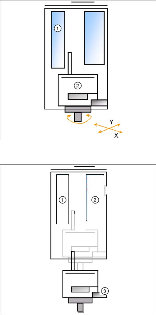
10.2.3 Preparations for Component Pickup (Module 2)
Preparations for Component Pickup (Module 2)
10.2.3.1
10.2.3.1 Picking up the Component (Module 2)
Picking up the Component (Module 2)
Legend
1. Z motor
2. D motor
Pick up with module 1 finished
▪ The X and Y gantry axes move to the feeder track or
pickup position.
▪ During gantry positioning, the module 2 D-axis ro-
tates to the pickup angle.
▪ Communication to component trolley ‘Feeder ready’
opens feeder pickup window.
Legend
1. Z motor
2. Vacuum/air blast generator
3. Force sensor
▪ Z Axis position downwards with Standard Pick up
mode at 2 N Pick up force.
▪ At contact with the component the force increase up
to the programmed value.
▪ At this force level the End signal is triggered and the
Vacuum controlling is activated.
10 P&P and TWIN Heads
10.2.4 Preparations for Placement (Module 1 Component) 10.2 Twin Head Pickup and Place Cycle
Student Guide SIPLACE D-Series (FSE) 187
10.2.4
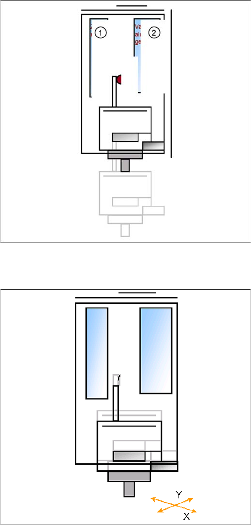
10.2.4 Preparations for Placement (Module 1 Component)
Preparations for Placement (Module 1 Component)
Legend
1. Z motor
2. Vacuum/air blast generator
▪ When Vacuum threshold ‘Pick up’ is measured the Z
Axis movement upwards start with Standard-posi-
tioning mode.
▪ Communication to comp. table ‘index Feeder’ when
the Z Axis reached the "safety height" position.
▪ At end signal Z Axis top -> Vacuum check ‘comp. on
nozzle’
▪ The D-axis is rotated to the placement angle (so that
only the component correction angle needs to be ro-
tated after centering).
▪ Prepare optical centering with module 1
▪ The X/Y gantry axes move to the corrected place-
ment position.
▪ The D-axis rotates by the placement angle correction
value.
10 P&P and TWIN Heads
10.3 P&P Head Main Board 10.2.4 Preparations for Placement (Module 1 Component)
188 Student Guide SIPLACE D-Series (FSE)
10.2.4.1
10.2.4.1 Placement (Module 1 Component)
Placement (Module 1 Component)
10.3
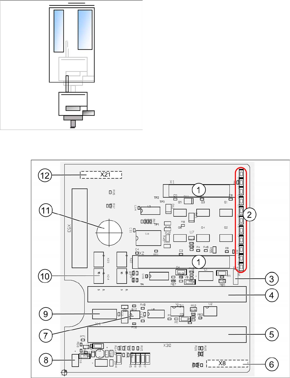
10.3 P&P Head Main Board
P&P Head Main Board
P&P head main board [00352833-xx]
▪ The Z axis moves downwards in standard mode (2 N
contact force).
▪ The Force increase up to the programmed level after
contact of the component on the PCB.
▪ With this Force signal the End signal is set. The air
blast control is activated too.
▪ At air blast level for placement ..
▪ The next placement sequence is prepared for a mod-
ule 2 component.