00195440-05-SG_D-Series_FSE-EN.pdf - 第188页
10 P&P and TWIN Heads 10.3 P&P Head Main Board 10.2.4 Pr eparations for Placement (Modu le 1 Component ) 188 Student Guide SIPLACE D-Series (FSE) 10.2.4.1 1 0 . 2 . 4 . 1 P la c e m e n t ( M o d u le 1 C o m p o…
10 P&P and TWIN Heads
10.2.4 Preparations for Placement (Module 1 Component) 10.2 Twin Head Pickup and Place Cycle
Student Guide SIPLACE D-Series (FSE) 187
10.2.4
10.2.4 Preparations for Placement (Module 1 Component)
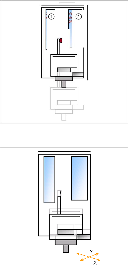
Preparations for Placement (Module 1 Component)
Legend
1. Z motor
2. Vacuum/air blast generator
▪ When Vacuum threshold ‘Pick up’ is measured the Z
Axis movement upwards start with Standard-posi-
tioning mode.
▪ Communication to comp. table ‘index Feeder’ when
the Z Axis reached the "safety height" position.
▪ At end signal Z Axis top -> Vacuum check ‘comp. on
nozzle’
▪ The D-axis is rotated to the placement angle (so that
only the component correction angle needs to be ro-
tated after centering).
▪ Prepare optical centering with module 1
▪ The X/Y gantry axes move to the corrected place-
ment position.
▪ The D-axis rotates by the placement angle correction
value.
10 P&P and TWIN Heads
10.3 P&P Head Main Board 10.2.4 Preparations for Placement (Module 1 Component)
188 Student Guide SIPLACE D-Series (FSE)
10.2.4.1
10.2.4.1 Placement (Module 1 Component)
Placement (Module 1 Component)
10.3
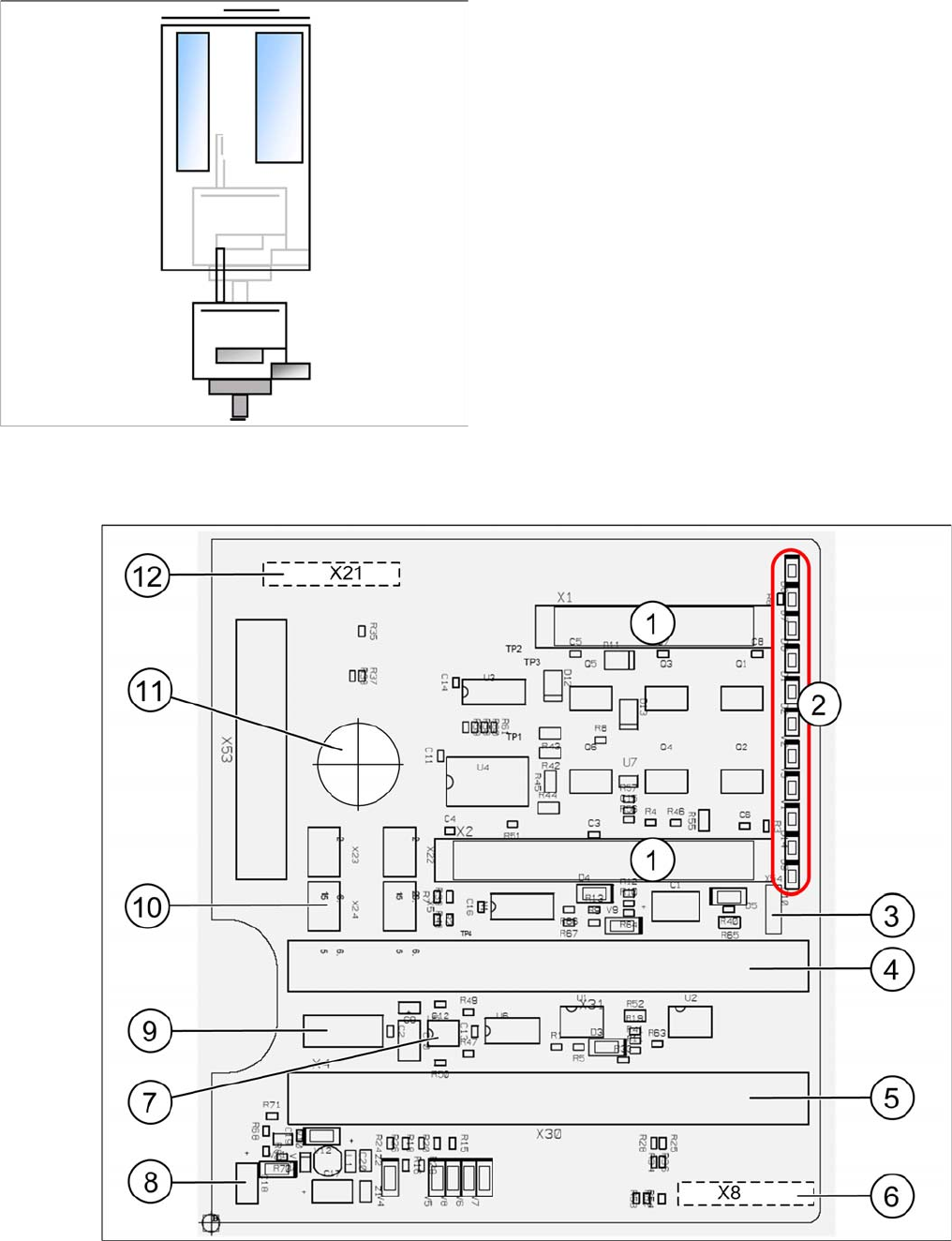
10.3 P&P Head Main Board
P&P Head Main Board
P&P head main board [00352833-xx]
▪ The Z axis moves downwards in standard mode (2 N
contact force).
▪ The Force increase up to the programmed level after
contact of the component on the PCB.
▪ With this Force signal the End signal is set. The air
blast control is activated too.
▪ At air blast level for placement ..
▪ The next placement sequence is prepared for a mod-
ule 2 component.

10 P&P and TWIN Heads
10.2.4 Preparations for Placement (Module 1 Component) 10.3 P&P Head Main Board
Student Guide SIPLACE D-Series (FSE) 189
Legend
The main board is mounted directly on the P&P head. This board is connected to the head adapter board
via two flat ribbon cables.
To (2) LEDs (description sequence downwards):
1 2 connectors for the 16 bit CAN Bus processor
(not used for X/D1/D1i/D3)
7 EEPROM storage the head specific data (
Head exchange, Reference run)
2 LEDs (see below) 8 Power supply 15 V for the Track signals D-
Axis (at the moment deactivated via the jump-
er X54)
3 X54 Jumper at the moment ON with the new
force measurement board set to OFF (see
LED V2/V_SP) 9 X4 Connector track signals Z-axis
4 Connectors for flat ribbon cable of head
adapter (gantry head distributor)
10 Connector pneumatic valve (return unit)
5 Connectors for flat ribbon cable of head
adapter (gantry head distributor)
11 Hole for pneumatic hose to the vacuum gen-
erator
6 X8: Flex-Cable (Signals: Track signals D-Ax-
is, Power supply Z-Axis/D-Axis, Z-Tempera-
ture and, SPI Bus)
12 X21 connector for vacuum generator
LED labels Color Description
D8 Green Initializing the retract unit
D7 KLEMM Green Display showing that the return cylinder has been moved out and down-
wards.
D6 BERO - Without function (previously: proximity switch for Z-axis up)
D1 DRUCK - Without function (Z pressure)
D2 KLEMM Yellow Display showing that the return cylinder has been moved out and down-
wards.
V2 V_SP - No function
V3 15V_ Green Display showing that voltage supply is OK
V1 TEMP Green Temperature of Z-axis motor is OK
D14 ALARM Red Before initializing, CAN Bus briefly red, then off
D9 DRUCK - No function
D10 24V+ Green Display showing that DC voltage supply is OK.