00195440-05-SG_D-Series_FSE-EN.pdf - 第190页
10 P&P and TWIN Heads 10.4 Nozzle Changer Position and Assembly 10.4.1 Nozzle Changer Position in D3 190 Student Guide SIPLACE D-Series (FSE) 10.4 1 0 . 4 N o z z le C h a n g e r P o s it io n a n d A s s e m b ly N…
10 P&P and TWIN Heads
10.2.4 Preparations for Placement (Module 1 Component) 10.3 P&P Head Main Board
Student Guide SIPLACE D-Series (FSE) 189
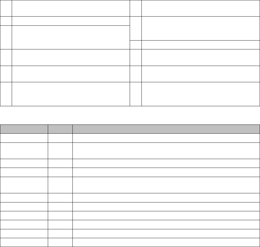
Legend
The main board is mounted directly on the P&P head. This board is connected to the head adapter board
via two flat ribbon cables.
To (2) LEDs (description sequence downwards):
1 2 connectors for the 16 bit CAN Bus processor
(not used for X/D1/D1i/D3)
7 EEPROM storage the head specific data (
Head exchange, Reference run)
2 LEDs (see below) 8 Power supply 15 V for the Track signals D-
Axis (at the moment deactivated via the jump-
er X54)
3 X54 Jumper at the moment ON with the new
force measurement board set to OFF (see
LED V2/V_SP) 9 X4 Connector track signals Z-axis
4 Connectors for flat ribbon cable of head
adapter (gantry head distributor)
10 Connector pneumatic valve (return unit)
5 Connectors for flat ribbon cable of head
adapter (gantry head distributor)
11 Hole for pneumatic hose to the vacuum gen-
erator
6 X8: Flex-Cable (Signals: Track signals D-Ax-
is, Power supply Z-Axis/D-Axis, Z-Tempera-
ture and, SPI Bus)
12 X21 connector for vacuum generator
LED labels Color Description
D8 Green Initializing the retract unit
D7 KLEMM Green Display showing that the return cylinder has been moved out and down-
wards.
D6 BERO - Without function (previously: proximity switch for Z-axis up)
D1 DRUCK - Without function (Z pressure)
D2 KLEMM Yellow Display showing that the return cylinder has been moved out and down-
wards.
V2 V_SP - No function
V3 15V_ Green Display showing that voltage supply is OK
V1 TEMP Green Temperature of Z-axis motor is OK
D14 ALARM Red Before initializing, CAN Bus briefly red, then off
D9 DRUCK - No function
D10 24V+ Green Display showing that DC voltage supply is OK.
10 P&P and TWIN Heads
10.4 Nozzle Changer Position and Assembly 10.4.1 Nozzle Changer Position in D3
190 Student Guide SIPLACE D-Series (FSE)
10.4
10.4 Nozzle Changer Position and Assembly
Nozzle Changer Position and Assembly
10.4.1
10.4.1 Nozzle Changer Position in D3
Nozzle Changer Position in D3
The D1/D1i machine has a TWIN Head nozzle changer with a 2x5 magazine block arrangement.
10.4.2
10.4.2 Assembly of Nozzle Changer Magazines
Assembly of Nozzle Changer Magazines
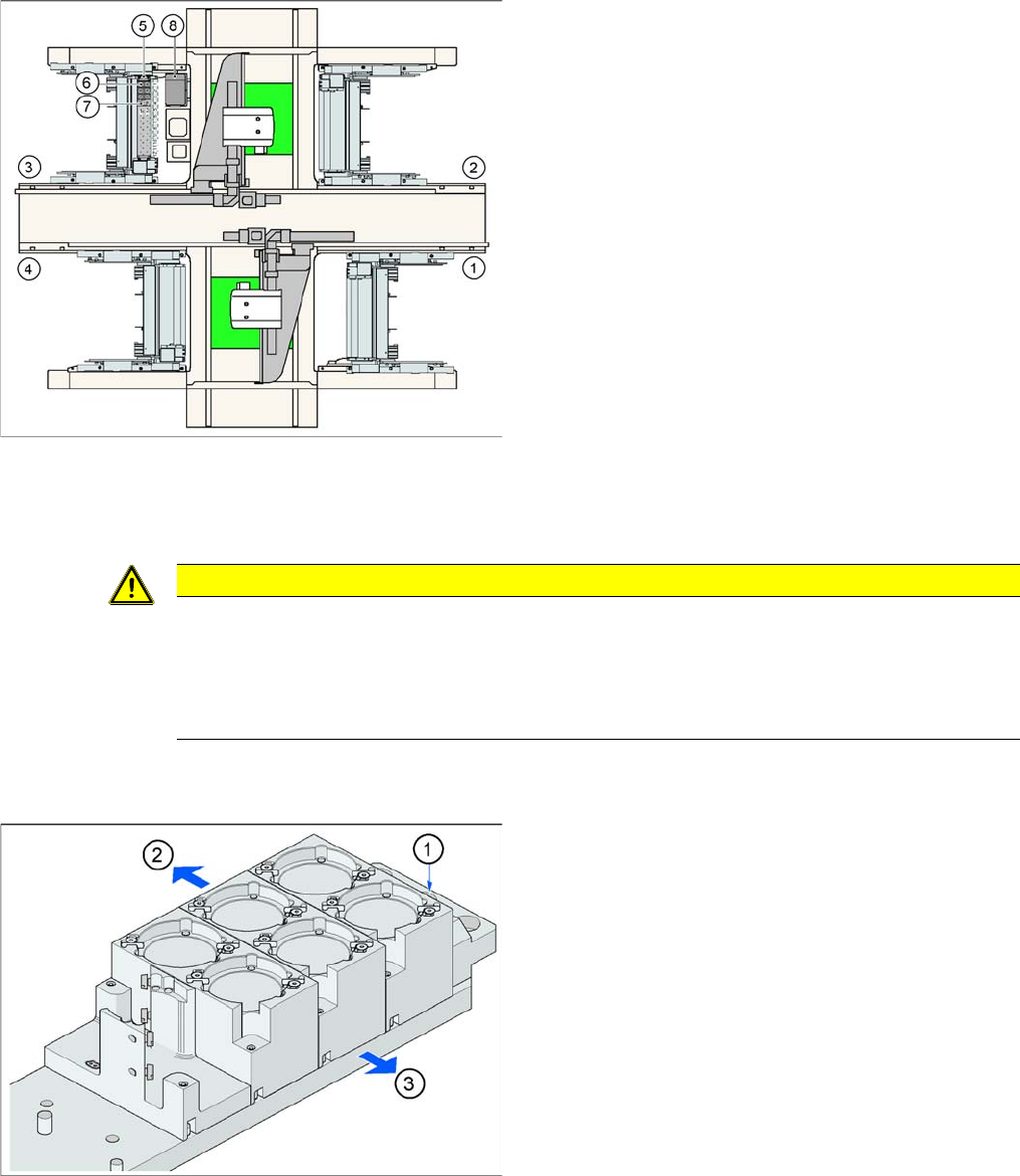
Position of "standard nozzle changer" – sector 3 shown
here (X2 shown as example)
Legend
1. Feeder area 1
2. Feeder area 2
3. Feeder area 3
4. Feeder area 4
5. Nozzle changer garage 1
6. Standard magazine
7. Magazine for special nozzles or grippers
8. Component reject bin
CAUTION
The magazines X/D3 magazines are therefore not compatible with D1/D1i magazines and vice
versa.
Note the change in height of the measurement fiducials at the magazines.
The magazine fixture drillings are no longer centrally aligned to the nozzle pickup, as in the case
of the X and D3 machines.
Fitting the magazines (X/D3 machine)
Der Pipettenwechsler ist zusammen mit dem Leer-
gurtleitkanal an der Docking Unit befestigt. The maga-
zines are seated on a common support. They are
centered with two parallel pins and fixed in place with two
countersunk screws.
Legend
1. Marking hole for nozzle changer carrier
2. Operator side (changeover table side)
3. Arrow pointing towards the PCB conveyor
Align the nozzle changer so that the marking hole (item
1) is on the left, as viewed by the operator (at the change-
over table side).
10 P&P and TWIN Heads
10.4.3 Functions 10.4 Nozzle Changer Position and Assembly
Student Guide SIPLACE D-Series (FSE) 191
10.4.3
10.4.3 Functions
Functions
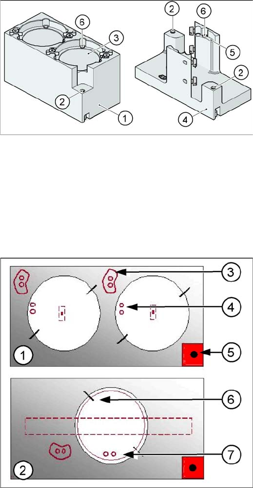
The magazine for standard nozzles has 1 positioning fiducial for position detection, while the magazine
for special nozzles/grippers has two positioning fiducials. The nozzles are fixed by balls in the garage.
They are then either locked or released for removal, depending on the direction of rotation of the DP axis.
Position of the nozzle in the magazines
There is another special nozzle for the Twin head, the so-called low force nozzle. This requires a special
garage, which is not listed here.
Magazine for standard and special nozzles (HF/X/D3 ma
-
chine shown here as example)
Legend
1. Standard magazine
2. Positioning fiducial
3. Nozzle garage
4. Magazine for special nozzles
5. Nozzle garage
6. Balls for fixing the nozzles
Legend
1. Double magazine for standard nozzles (pickup angle
SW 505 = 184°)
2. Magazine for special nozzles or grippers (pickup an-
gle SW 505 = 275°)
3. Index pins for correct positioning of nozzles in maga-
zine
4. Position of nozzle with the holes for the index pins.
5. Calibration fiducial for determining the magazine po-
sition
6. Nozzle centering pins
7. The magazines for the special nozzles are turned by
90° degrees.