00195440-05-SG_D-Series_FSE-EN.pdf - 第191页
10 P&P and TWIN Heads 10.4.3 Functions 10.4 Nozzle Changer Position and Assembly Student Guide SIPLACE D-Series (FSE) 191 10.4.3 1 0 . 4 . 3 F u n c t io n s Functions The magazine for standard nozzles has 1 position…
10 P&P and TWIN Heads
10.4 Nozzle Changer Position and Assembly 10.4.1 Nozzle Changer Position in D3
190 Student Guide SIPLACE D-Series (FSE)
10.4
10.4 Nozzle Changer Position and Assembly
Nozzle Changer Position and Assembly
10.4.1
10.4.1 Nozzle Changer Position in D3
Nozzle Changer Position in D3
The D1/D1i machine has a TWIN Head nozzle changer with a 2x5 magazine block arrangement.
10.4.2
10.4.2 Assembly of Nozzle Changer Magazines
Assembly of Nozzle Changer Magazines
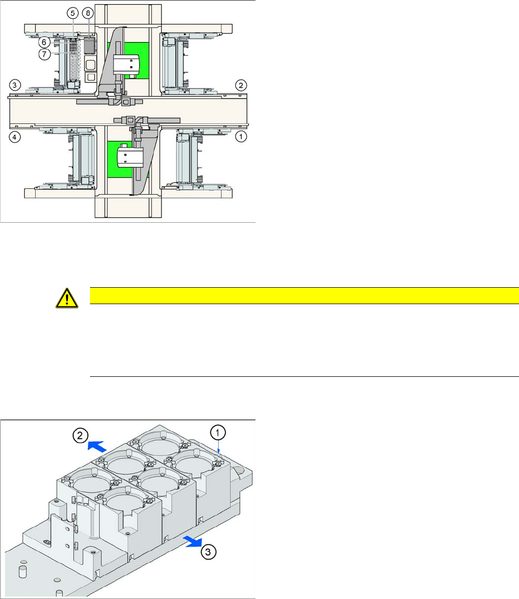
Position of "standard nozzle changer" – sector 3 shown
here (X2 shown as example)
Legend
1. Feeder area 1
2. Feeder area 2
3. Feeder area 3
4. Feeder area 4
5. Nozzle changer garage 1
6. Standard magazine
7. Magazine for special nozzles or grippers
8. Component reject bin
CAUTION
The magazines X/D3 magazines are therefore not compatible with D1/D1i magazines and vice
versa.
Note the change in height of the measurement fiducials at the magazines.
The magazine fixture drillings are no longer centrally aligned to the nozzle pickup, as in the case
of the X and D3 machines.
Fitting the magazines (X/D3 machine)
Der Pipettenwechsler ist zusammen mit dem Leer-
gurtleitkanal an der Docking Unit befestigt. The maga-
zines are seated on a common support. They are
centered with two parallel pins and fixed in place with two
countersunk screws.
Legend
1. Marking hole for nozzle changer carrier
2. Operator side (changeover table side)
3. Arrow pointing towards the PCB conveyor
Align the nozzle changer so that the marking hole (item
1) is on the left, as viewed by the operator (at the change-
over table side).
10 P&P and TWIN Heads
10.4.3 Functions 10.4 Nozzle Changer Position and Assembly
Student Guide SIPLACE D-Series (FSE) 191
10.4.3
10.4.3 Functions
Functions
The magazine for standard nozzles has 1 positioning fiducial for position detection, while the magazine
for special nozzles/grippers has two positioning fiducials. The nozzles are fixed by balls in the garage.
They are then either locked or released for removal, depending on the direction of rotation of the DP axis.
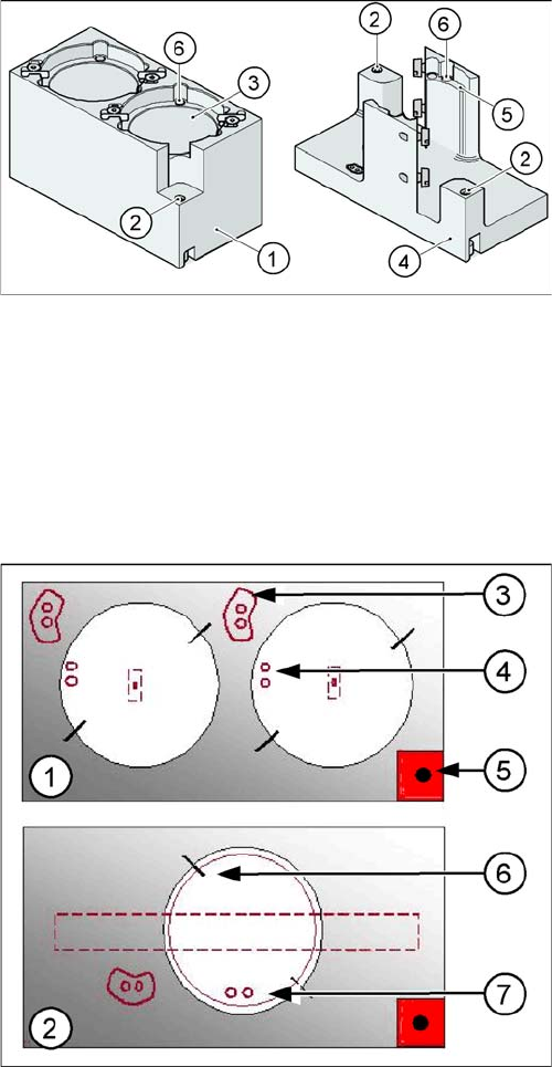
Position of the nozzle in the magazines
There is another special nozzle for the Twin head, the so-called low force nozzle. This requires a special
garage, which is not listed here.
Magazine for standard and special nozzles (HF/X/D3 ma
-
chine shown here as example)
Legend
1. Standard magazine
2. Positioning fiducial
3. Nozzle garage
4. Magazine for special nozzles
5. Nozzle garage
6. Balls for fixing the nozzles
Legend
1. Double magazine for standard nozzles (pickup angle
SW 505 = 184°)
2. Magazine for special nozzles or grippers (pickup an-
gle SW 505 = 275°)
3. Index pins for correct positioning of nozzles in maga-
zine
4. Position of nozzle with the holes for the index pins.
5. Calibration fiducial for determining the magazine po-
sition
6. Nozzle centering pins
7. The magazines for the special nozzles are turned by
90° degrees.

10 P&P and TWIN Heads
10.5 Overview of Positioning Times for TwinHead 10.4.3 Functions
192 Student Guide SIPLACE D-Series (FSE)
10.5
10.5 Overview of Positioning Times for TwinHead
Overview of Positioning Times for TwinHead
Positioning times for TwinHead
Axis Mode/range Positioning time
Z Absolute positioning, free space/travel range 90000 digits =
45000 µm (resolution 0.5 µm)
75 ms +/-3 ms
Z Absolute positioning, free space/travel range 54200 digits = 27100
µm (resolution 0.5 µm)
57 ms +/-3 ms
Z Current sensor (for force measurement) on conveyor edge 516
nozzle travel profile 5, force 2 N
approx. 78 ms*
*see notes below
Z Current sensor (for force measurement) on conveyor edge 516
nozzle travel profile 7, force 5 N
approx. 78 ms*
*see notes below
Z Current sensor (for force measurement) on conveyor edge 516
nozzle travel profile 7, force 10 N
approx. 65 ms*
*see notes below
Z Current sensor (for force measurement) on conveyor edge 516
nozzle travel profile 25, force 15 N
approx. 70 ms*
*see notes below
d 10000 digits = 10 degrees 90 ms +/-10 ms*
*see notes below
d 90000 digits = 90 degrees 150 ms +/-20 ms*
*see notes below
d 180000 digits = 180 degrees 190 ms +/-20 ms*
*see notes below
NOTICE
Z Axis
The Z axis positioning time in the current or force sensor mode does not permit direct conclu-
sions about the functions. To check the function of these modes, you need to record oscillo-
grams or perform a force measurement during placement.
NOTICE
D Axis
The positioning times between the left and right turns of the sleeve may deviate from one an-
other considerably. However, the time characteristic of the TwinHead in not critical, due to the
placement process.