00195440-05-SG_D-Series_FSE-EN.pdf - 第198页
11 Component Handling 11.1 Overview 11.1.3 Changeover Table 198 Student Guide SIPLACE D-Series (FSE) 11.1.3 1 1 . 1 . 3 C h a n g e o v e r T a b le Changeover Table Bulkcase feeder pneu - matic supply 12 location s 15 l…

11 Component Handling
11.1.2 Changeover Table Construction 11.1 Overview
Student Guide SIPLACE D-Series (FSE) 197
11.1.2
11.1.2 Changeover Table Construction
Changeover Table Construction
The S feeder changeover tables on the 4 machine types in the D/Di-series have the following common/
different features:
Feeders: Tapes, bulkcase, linear feeder, Siplace S feeder (F4, F5,S20, S23,
S25HM, S27HM, HS50, HS50+,HS60), OEM feeder, surftape feeder
(8, 12, 16, 24 mm), manual trays
Interface to the ma-
chine
Plug-in connection to machine
- Power supply
- CAN bus connection
- Closing the safety loop
- Compressed air connection
- Splice point recognition connection (optional)
Changeover table
height
depend from the machine height:
830 mm ± 15 mm (standard)
900 mm ± 15 mm (SMEMA)
930 mm ± 15 mm (SMEMA)
950 mm ± 15 mm (SMEMA)
Assembly D4/D4i D3 D2/D2i D1/D1i
Feeder table plate HS x0 compati-
ble (440 mm)
X machine with S
table, compatible
Widened table, new (562 mm)
Changeover table po-
sition in the machine
1 Location 1 D2/D2i
position
Location 1 D1/D1i
position
Magnetic strip Glued and
screwed
Glued and screwed
Connection type Harting plug on
flexible connec-
tion
ODU connector,
fixed - as central
front plug.
Harting plug on flexible connection
Different coding to D4/D4i
Tape cutter control Standard communication for F- bis D/Di-Maschine (different Art-Nrn., de-
pending on eSW)
Feeder location 12 15
CAN Bus 500 KBit/s 1 MBit/s
Fitting the changeover
table
See D2//D2i/D1/
D1i
Table automatical-
ly connected by ta-
ble docking unit
Move in table; connect table; lower ta-
ble and close feeder cover flap
Pneumatic switch See D2/D2i/D1/
D1i
---- In the machine, always in lowered po-
sition and track 1 always with feeder /
safety cover (if fitted) ensures safe ta-
ble position; safety cover is always on
table plate.
Table plate for WPC
option
--- Yes for STP 1
Options
Feeder cover flap Yes Option for DLM PA Yes No
Holder for 3rd tape reel 12 loca-
tions.(HS50 com-
patible?)
15 locations (HF
compati-
ble?)119623
15 locations
Additional Tape Reel
Container (only for Di-
series)
Max 2 containers
per COT
---- Max 2 containers per COT
11 Component Handling
11.1 Overview 11.1.3 Changeover Table
198 Student Guide SIPLACE D-Series (FSE)
11.1.3
11.1.3 Changeover Table
Changeover Table
Bulkcase feeder pneu-
matic supply
12 locations 15 locations
142335
15 locations
"Feeder claw" 12 locations 15 locations
Lifting/lowering device
(only function when
changeover table is
connected)
Yes No
(via front connec-
tor plug)
Yes Yes
Voltage supply for
Feeder Control Unit
(FCU)
8 VDC for control logic
30 VDC for feeder supply, including all linear feeders (24 VAC no longer need-
ed)
S feeder C&P12 bis 32 mm width bis 32 mm width
S feeder C&P6 bis 44 mm b width
S feeder P&P All up to 19 mm
component height
S feeder TWIN All up to 25 mm
component height
Assembly D4/D4i D3 D2/D2i D1/D1i
11 Component Handling
11.1.3 Changeover Table 11.2 Setting the Height of the Changeover Table
Student Guide SIPLACE D-Series (FSE) 199
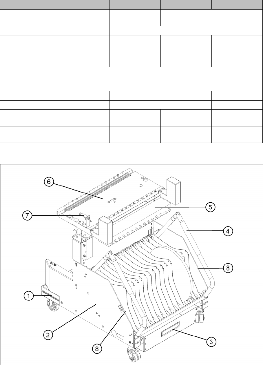
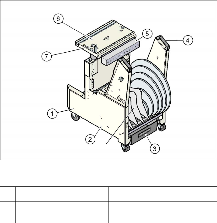
Overview: Changeover table structure (D1/D1i/D2/D2i shown as example)
Legend
11.2
11.2 Setting the Height of the Changeover Table
Setting the Height of the Changeover Table
The changeover table can be manually set to the following PCB transport heights
▪ 830 mm PCB transport height
▪ 900 mm PCB transport height
▪ 930 mm PCB transport height
▪ 950 mm PCB transport height
1 Moveable base with fixed and guide castor 5 Communication unit
2 Tape reels container 6 Table plate
3 Tape waste container 7 Switch for lowering the changeover table
4 Handle 8 Storage room for extra partition plates or
setup lists, next to the handles