00195440-05-SG_D-Series_FSE-EN.pdf - 第201页
11 Component Handling 11.3.1 Holder for the Third Tap e Reel on 3 x 8 mm S Feeder Modules 11.3 Optional Extension on the COT Student Guide SIPLACE D-Series (FSE) 201 11.3 1 1 . 3 O p t io n a l E x t e n s io n o n t h e…
11 Component Handling
11.2 Setting the Height of the Changeover Table 11.2.1 Adjusting the Component Trolley Height
200 Student Guide SIPLACE D-Series (FSE)
11.2.1
11.2.1 Adjusting the Component Trolley Height
Adjusting the Component Trolley Height
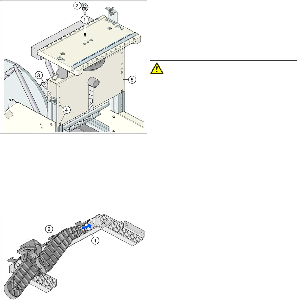
► Screw the eyebolt into the M12 hole provided (1) on the component trolley table.
► Hook the leverage device into the eyebolt (2).
► Tighten the rope of the leverage device.
► Loosen the 8 hexagon socket-head screws, M6x12 (4).
► Lift or lower the component trolley table to the required height. Make sure that the hole for the re-
quired height in the bridge (5) is level with the top hole in the vertical profile bar (3).
► Fasten the bridge (5) to the vertical profile bar (3) with the 8 hexagon socket-head screws M6x12 (4).
► Unscrew the eyebolt from the component trolley table.
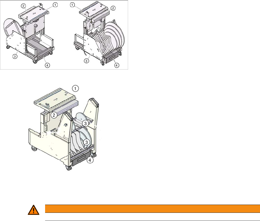
Changeover table (D4 shown as example)
Legend
1. Feeder table plate
2. Communication unit
3. Tape container
4. Waste container for tape cuttings
Changeover table (D4i shown as example)
1.
WARNING
Lift all feeder modules off the component trolley table plate.
11 Component Handling
11.3.1 Holder for the Third Tape Reel on 3 x 8 mm S Feeder Modules 11.3 Optional Extension on the COT
Student Guide SIPLACE D-Series (FSE) 201
11.3
11.3 Optional Extension on the COT
Optional Extension on the COT
When using these options, do not forget that the D1/D1i/D2/D2i and D4/D4i machines have different ta-
ble widths.
11.3.1
11.3.1 Holder for the Third Tape Reel on 3x8mm S Feeder Modules
Holder for the Third Tape Reel on 3 x 8 mm S Feeder Modules
The following parts are needed for the middle tape reel:
▪ An adapter plate to hold the tape reel holder (1)
▪ One tape reel holder for every two feeder modules (2).
The adapter plate is fixed with four fillister head screws to the component trolley, while the tape reel hold-
er is plugged into the square openings in the adapter plate.
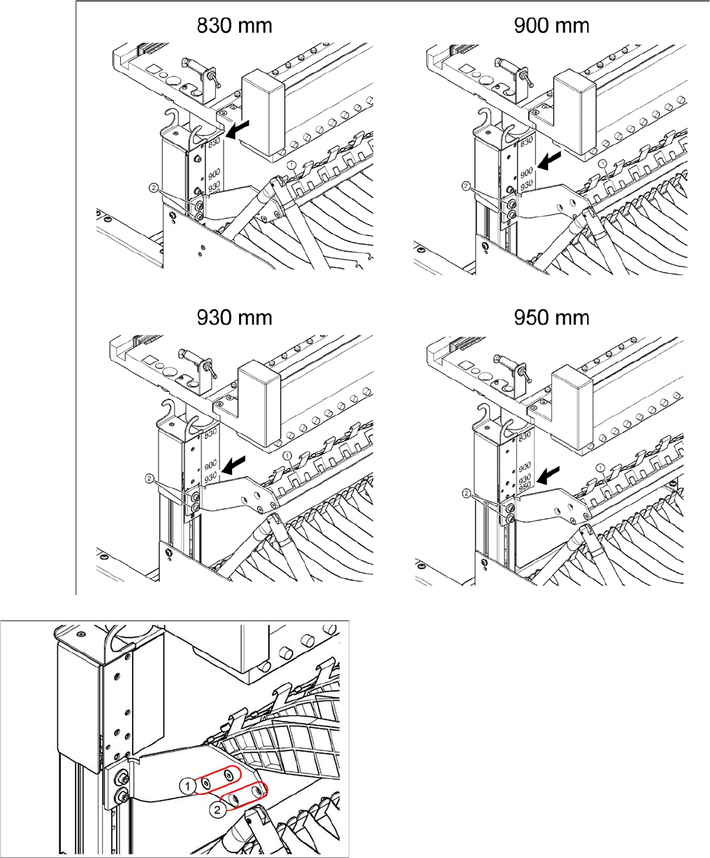
Installation position of adapter plate
Due to the various machine heights, D/Di machines have four different installation positions for the hold-
er of the third tape reel (adapter plate).
Position of eyebolt on component trolley
Legend
1. M12 hole drilled for eyebolt
2. Eyebolt DIN 580 M12-St
3. Vertical profile bar
4. 8 x hexagon socket-head screw SN 62355, M6x12
5. Bridge
CAUTION! Always use the fit-up aid (screwed
eyelet) to fix the table plate, irrespective of whether you
want to raise or lower the component trolley.
Holder for middle tape reel in 3 x 8 mm S feeder mod
-
ules, with D3 shown as example (the diagram does not
show the actual installation position in the changeover ta
-
ble - the side part of the adapter plate is vertical there).
Legend
1. Adapter plate
2. Tape reel holder
Feeder modules of type 3 x 8 mm-S transport compo-
nents in three feeder tracks to the pickup position. The
tape reels on the two outer tracks are located between
the divider sheets in the tape container. The middle tape
reel is located above the two tape reels for the outer
tracks.
11 Component Handling
11.3 Optional Extension on the COT 11.3.1 Holder for the Third Tape Reel on 3 x 8 mm S Feeder Modules
202 Student Guide SIPLACE D-Series (FSE)
Legend
1. Adapter plate installation position without splice de-
tection
2. Adapter plate installation position with splice detec-
tion