00195440-05-SG_D-Series_FSE-EN.pdf - 第202页
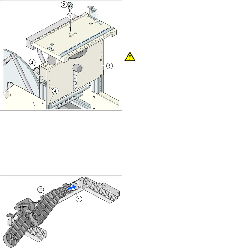
11 Component Handling 11.3 Optional Extension on the COT 11.3.1 Holder for the Third T a pe Reel on 3 x 8 mm S Feeder Modules 202 Student Guide SIPLACE D-Series (FSE) Legend 1. Adapt er plate installa tion position witho…
11 Component Handling
11.3.1 Holder for the Third Tape Reel on 3 x 8 mm S Feeder Modules 11.3 Optional Extension on the COT
Student Guide SIPLACE D-Series (FSE) 201
11.3
11.3 Optional Extension on the COT
Optional Extension on the COT
When using these options, do not forget that the D1/D1i/D2/D2i and D4/D4i machines have different ta-
ble widths.
11.3.1
11.3.1 Holder for the Third Tape Reel on 3x8mm S Feeder Modules
Holder for the Third Tape Reel on 3 x 8 mm S Feeder Modules
The following parts are needed for the middle tape reel:
▪ An adapter plate to hold the tape reel holder (1)
▪ One tape reel holder for every two feeder modules (2).
The adapter plate is fixed with four fillister head screws to the component trolley, while the tape reel hold-
er is plugged into the square openings in the adapter plate.
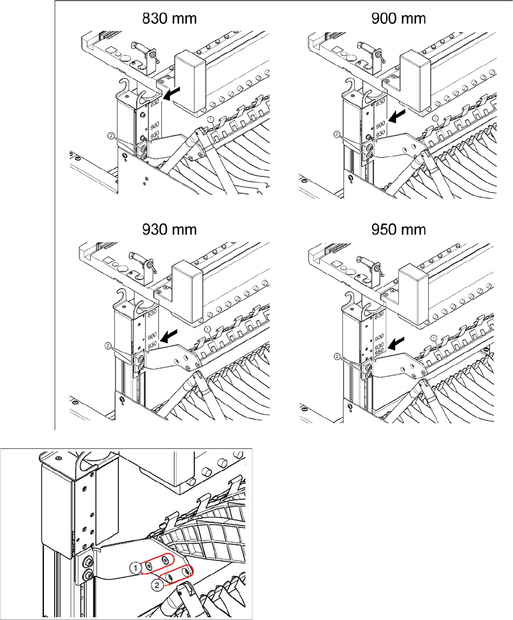
Installation position of adapter plate
Due to the various machine heights, D/Di machines have four different installation positions for the hold-
er of the third tape reel (adapter plate).
Position of eyebolt on component trolley
Legend
1. M12 hole drilled for eyebolt
2. Eyebolt DIN 580 M12-St
3. Vertical profile bar
4. 8 x hexagon socket-head screw SN 62355, M6x12
5. Bridge
CAUTION! Always use the fit-up aid (screwed
eyelet) to fix the table plate, irrespective of whether you
want to raise or lower the component trolley.
Holder for middle tape reel in 3 x 8 mm S feeder mod
-
ules, with D3 shown as example (the diagram does not
show the actual installation position in the changeover ta
-
ble - the side part of the adapter plate is vertical there).
Legend
1. Adapter plate
2. Tape reel holder
Feeder modules of type 3 x 8 mm-S transport compo-
nents in three feeder tracks to the pickup position. The
tape reels on the two outer tracks are located between
the divider sheets in the tape container. The middle tape
reel is located above the two tape reels for the outer
tracks.
11 Component Handling
11.3 Optional Extension on the COT 11.3.1 Holder for the Third Tape Reel on 3 x 8 mm S Feeder Modules
202 Student Guide SIPLACE D-Series (FSE)
Legend
1. Adapter plate installation position without splice de-
tection
2. Adapter plate installation position with splice detec-
tion
11 Component Handling
11.3.2 Additional Tape Reel Container for Di-series 11.3 Optional Extension on the COT
Student Guide SIPLACE D-Series (FSE) 203
11.3.2
11.3.2 Additional Tape Reel Container for Di-series
Additional Tape Reel Container for Di-series
11.3.3
11.3.3 External Power Supply
External Power Supply
To keep the time for setup changeovers to a minimum, the component trolleys can be set up at an ex-
ternal setup location. The feeder module functions and settings can also be checked there as part of the
preparations for operation. An external power supply unit is available for this purpose. The component
trolley is supplied with the required operating voltage and compressed air via a supply cable.
Technical data
Scope of delivery
▪ Voltage supply
▪ Power supply cables (European and US standards)
▪ Connection cables for the three machine types D1/D1i/D2/D2i, D3 and D4/D4i
Max. tape reel size Installation position of 3rd
holder
830 mm without splice detection 43.2 mm (17") Up
830 mm with splice detection 38.1 mm (15") Down
900 mm with splice detection 48.3 mm (19") Up
900 mm without splice detection 48.3 mm (19") Down
930 / 950 mm with or without splice detection 48.3 mm (19") Either
NOTICE
Cause of Hazard
For further details, refer to the installation guide for the "Adapter 3rd tape reel".
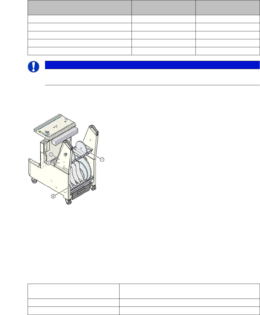
Additional Tape Reel Container (For only Di-Series)
Additional tape reel container is design to hold the 3
rd
reel
component from the 3 x 8mm Feeder. Each Di-series
COT is able to fix up to maximum 2 pcs of the additional
tape reel containers.
Legend
1. Each container is fixed to the COT via 4 screws
2. Height of container depends on the mounting screw
holes (High Height)
3. Height of container depends on the mounting screw
holes (Low Height)
4. Partition Plates.
Line voltage 230 V~ ±5 %
120 V~ ±5 %
Compressed air connection max. 1.0 MPa (10 bar)
Output pressure Adjustable via valve