00195440-05-SG_D-Series_FSE-EN.pdf - 第205页
11 Component Handling 11.3.6 Additional Communication unit for splice detection 11.4 P neumatic Tape Cutter Student Guide SIPLACE D-Series (FSE) 205 11.3.6 1 1 . 3 . 6 A d d it io n a l C o m m u n ic a t io n u n it f o…
11 Component Handling
11.3 Optional Extension on the COT 11.3.4 Compressed Air Supply for Bulkcase Feeders
204 Student Guide SIPLACE D-Series (FSE)
11.3.4
11.3.4 Compressed Air Supply for Bulkcase Feeders
Compressed Air Supply for Bulkcase Feeders
11.3.5
11.3.5 Fixtures for S-Feeders
Fixtures for S-Feeders
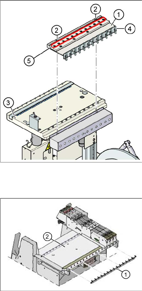
Compressed air supply for bulkcase feeders
Legend
1. Compressed air distributor
2. 2 x screw DIN 912, M8x20
3. Feeder table plate
4. Brackets
5. Compressed air connections for bulkcase feeders
Bulkcase feeders require compressed air. The optional
compressed air supply for bulkcase feeders is available
for this purpose.
Installation is easy. The compressed air distributor (1) is
fixed with two screws (2) to the changeover table (3). The
compressed air distributor is then connected to the com-
ponent trolley compressed air supply. At the back of the
compressed air distributor, there is a row of brackets (4).
These fix the bulkcase feeder modules to the changeover
table, ensuring optimum compressed air supply.
Feeder fixtures (HF shown as example)
Legend
1. Feeder fixtures
2. Changeover Table
The Feeder-Fixing is an additional mechanical safety
precaution. It prevents accidental movement of the feed-
er on the changeover table. It excludes a head crash risk
with a wrong positioned feeder. The feeder-fixation is
mounted on the front side of the changeover table. The
claws fix the feeder feet. A feeder clamp can be installed
for each of the component trolleys.

11 Component Handling
11.3.6 Additional Communication unit for splice detection 11.4 Pneumatic Tape Cutter
Student Guide SIPLACE D-Series (FSE) 205
11.3.6
11.3.6 Additional Communication unit for splice detection
Additional Communication unit for splice detection
11.3.7
11.3.7 Waffle Pack Changer (WPC)
Waffle Pack Changer (WPC)
To add a WPC4 in to a D1/D1i (D3: ab SR/MC 605) machine the following Steps are necessary:
► Remove COT Location 1BE-Tisch Stellplatz 1 (D3: Location 2)
► Remove the empty-tape duct assembly.
► Remove the waste slide.
► Remove the changeover table stopper.
► Fit the fixed changeover table WPC4 and screw tight.
► Assemble the empty tape canal
► Insert the WPC, lower and align.
11.4
11.4 Pneumatic Tape Cutter
Pneumatic Tape Cutter
Additional Communication unit for splice detection
An additional communication unit for the option Tracea-
bility with splice detection is necessary. The splice sen-
sors on the communication unit inform the station
software when a new component lot (reel) is spliced on.
This sets the new fill level for this component automatical-
ly.
Legend
1. The additional communication unit is screwed into
place, together with the changeover table communi-
cation unit.
NOTICE
Cause of Hazard
. Take care not to confuse the WPC4 title with the Station numbering single WPCs
NOTICE
Cause of Hazard
With D1/D1i-Machine the S-feeders are on the right side of WPC4
With D3-Machine S-Feeders are left of the WPC4.
NOTICE
Cause of Hazard
The D4/D4i machine is used as an example to describe the pneumatic cutter.
11 Component Handling
11.4 Pneumatic Tape Cutter 11.4.1 Overview of Pneumatic Cutter with Empty Tape Duct
206 Student Guide SIPLACE D-Series (FSE)
11.4.1
11.4.1 Overview of Pneumatic Cutter with Empty Tape Duct
Overview of Pneumatic Cutter with Empty Tape Duct
The pneumatic cutter is fixed to the machine frame with four screws and forms a unit with the empty tape
duct. It separates plastic, aluminum and paper tapes up to a maximum pocket depth of 25 mm. The tape
clippings fall down the waste slide, into the waste tape container of the component trolley.
The empty tape duct is designed to cover the cutting edges of the cutter (to avoid risk of injury), to guide
the empty component tapes to the cutter, to integrate the component reject container and accommodate
the C&P12 nozzle changer.
11.4.2
11.4.2 Structure and Function of the Pneumatic Tape Cutter
Structure and Function of the Pneumatic Tape Cutter
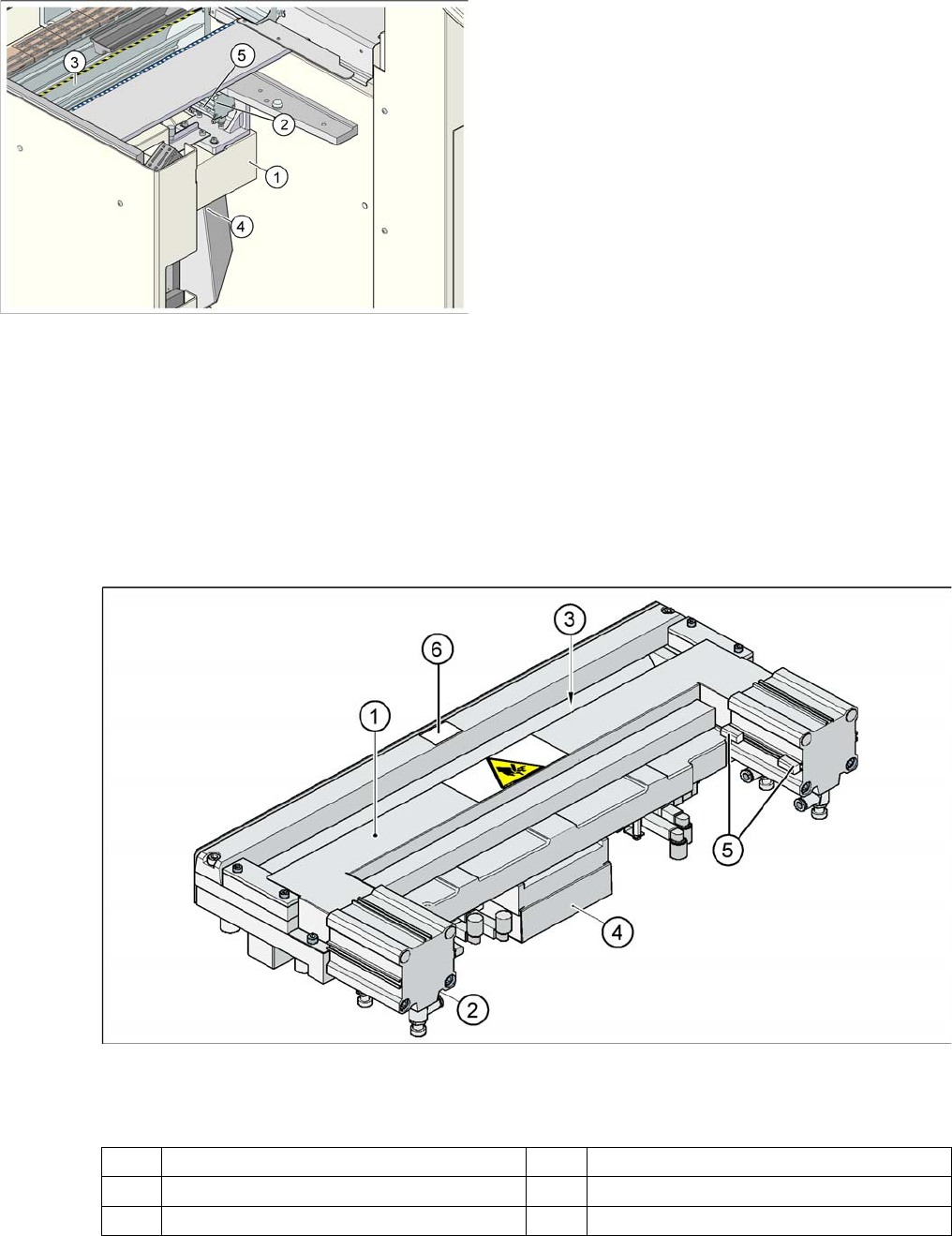
Pneumatic tape cutter
Legend
The empty tape duct guides the empty tapes through the opening (3) in the cutter.
Einzugsvorrichtung komplett (hier: D4/D4i)
Legend
1. Cross bar
2. Tape cutter
3. Empty Tape Duct
4. Waste slide
5. Proximity switch
1 Horizontal frame 4 Electronic control unit
2 Pneumatic cylinder 5 Proximity switch
3 Slot for empty tape 6 Fixed blade