00195440-05-SG_D-Series_FSE-EN.pdf - 第208页
11 Component Handling 11.4 Pneumatic Tape Cutter 11.4.4 Empty Tape Duct 208 Student Guide SIPLACE D-Series (FSE) The jumper for the CAN bus addressing must be set according to the corresponding location in the ma - chine…
11 Component Handling
11.4.3 Tape Cutter Control Unit 11.4 Pneumatic Tape Cutter
Student Guide SIPLACE D-Series (FSE) 207
The cutter is based on a horizontal frame (1) with a fixed cutting edge and a flexible blade, which is
moved by two short-stroke cylinders (2). At each forwards movement, the device cuts off the tape..
The proximity switch (5) signals the position of the short-stroke cylinder pistons and therefore of the cut-
ter blade. The control electronics (4) (under the cutter) register, for example, any components in the tape
which have not been cut. Cutting is only performed during the placement procedure. For operational
safety reasons, the tape cutter is integrated into the emergency stop circuit.
The tape cutter is activated when the gantry is moving to the placement position. Alternating one of the
cylinders start to front position. Once the first cylinder reaches the front position, the second cylinder is
started. Both signals ’blade in front position’ trigger control unit to withdraw both cylinders at the same
time.
11.4.2.1
11.4.2.1 Technical data
Technical data
11.4.2.2
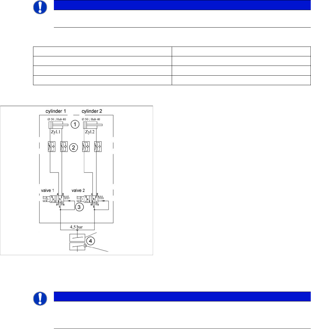
11.4.2.2 Pneumatic Scheme Tape Cutter
Pneumatic Scheme Tape Cutter
11.4.3
11.4.3 Tape Cutter Control Unit
Tape Cutter Control Unit
NOTICE
The cutter can be removed within about 15 minutes for service purposes. For detailed informa-
tion about dismantling, refer to the service manual.
Compressed air supply 0.5 MPa = 5.0 bar
Compressed air consumption 135 l/min.
Cycle time 1.5 sec per cut
Supply voltages 5 VDC, 24 VDC
Compressed air supply to tape cutter
Legend
1. Drive cylinder for cutter blade movement 40 mm
stroke
2. Adjustable throttle valve on the pneumatic cylinder
3. 5/2 way magnetic valve
4. 4.5 bar compressed air supply and 24 V voltage sup-
ply via the PCC safety relay
Cutter only active when protective hoods are closed
NOTICE
Control unit [03006411-xx] is replaced by CAN node module.
This version of the control unit is replaced by the backwards compatible CAN node [03052027-
xx] module.
11 Component Handling
11.4 Pneumatic Tape Cutter 11.4.4 Empty Tape Duct
208 Student Guide SIPLACE D-Series (FSE)
The jumper for the CAN bus addressing must be set according to the corresponding location in the ma-
chine.
11.4.3.1
11.4.3.1 FSE Note
FSE Note
11.4.4
11.4.4 Empty Tape Duct
Empty Tape Duct
The empty tape duct acts as a base for further modules:
▪ The removable nozzle reject container (3)
▪ The installation surface (5) for the C&P nozzle changer
▪ The nozzle stripping unit (4)
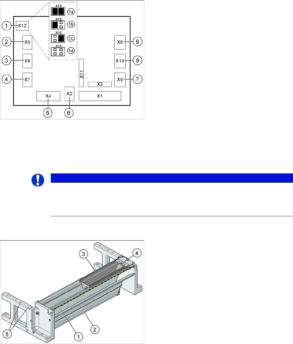
Jumper setting on the tape cutter unit (example of D4/D4i
shown)
Legend
1. X12 – Jumper for location code of cutter:
1a: Gantry 1
1b: Gantry 2
1c: Gantry 3
1d: Gantry 4
2. X5 – Voltage supply to valve (left)
3. X8 – Proximity switch for stroke cylinder out (left)
4. X7 – Proximity switch for stroke cylinder in (left)
5. X4 – CAN bus connection
6. X2 – Voltage supply for cutter +24 V and +5 V
7. X9 – Proximity switch for stroke cylinder in (left)
8. X10 – Proximity switch for stroke cylinder out (right)
9. X6 – Voltage supply to valve (right)
NOTICE
This tape cutter works at 500kbit/s CAN bus with the G01xxxxx eSW and at the 1Mbit/s CAN
bus with the G02xxxxx eSW.
A new tape cutter control unit (with downwards compatibility) (currently only available for X ma-
chines) can also perform nozzle changer control. The eSW to be loaded is the G03xxxxx.
Empty-tape duct with component reject container (D4/D4i
shown as example)
Legend
1. Inlet slot for empty tape
2. Outlet slot for the empty tape above the pneumatic
tape cutter
3. Nozzle reject container
4. Nozzle reject station
5. assembly surface for the nozzle changer
The empty tape duct receives empty tapes from the feed-
ers at the inlet gap (1) and guides these from the outlet
gap (2) to the cutting position of the pneumatic cutter.
This is where the tape is cut up and falls down the waste
slide, into the component trolley waste tape container.
Für die WPC4-Option ist ein auf 5 Fördererpositionen re-
duzierter Leergurtleitkanal verfügbar.
The empty tape duct is fixed to the pneumatic tape cutter
with four screws.

11 Component Handling
11.4.5 Feeder Modules 11.4 Pneumatic Tape Cutter
Student Guide SIPLACE D-Series (FSE) 209
11.4.5
11.4.5 Feeder Modules
Feeder Modules
S Feeder Any position possible at the D/Di-series locations.
Linear feeder Any position possible at the D/Di-series locations.
Waffle pack trays Carrier 51 (8,5 Feederplätze) /30 (5 Feederplätze) on COT 1 der D1/D1i.
only with disambled nozzle changers the C&P-Kopf