00195440-05-SG_D-Series_FSE-EN.pdf - 第217页
12 Modular Conveyor 12.1.12 Measuring Points and Belt Tensions for D1/D1 i/D2/D2i Co nveyor 12.1 Functions Student Guide SIPLACE D-Series (FSE) 217 12.1.12 1 2 . 1 . 1 2 M e a s u r in g P o in t s a n d B e lt T e n s i…

12 Modular Conveyor
12.1 Functions 12.1.11 Overview – Conveyor Systems in D/Di-Series
216 Student Guide SIPLACE D-Series (FSE)
Movement to LASER Time-controlled slow
speed
Lifting table
Clamping Upwards
Drive Pneumatic cylinder
Damper at top YES
Dual TSP lifting tables Can be coupled
PCB clamping length 368 mm Specified PCB clamping length: 460 mm
Assembly D2/D2i D1/D1i 3-part conveyor system
Conveyor control
TSP201 YES
Extension assembly for DT ---
SMEMA Option Can be switched via jumper and needs an
interface box and other cables between the
machines
Siemens PCB handling in-
terface
Standard
Conveyor (TSP) conversion
board
YES
Conveyor (TSP) side con-
version board
2 or 4 3 or 4
DIP switch, single conveyor 2, 4, 5 ON
1, 3, 6 OFF
2, 4 ON
1, 3, 5, 6
OFF
DIP switch (5) D2/D2i must be set, DIP
switch D1/D1i does not need to be set, as on
the label!
DIP switch, dual conveyor 1, 2, 4, 5 ON
3, 6 OFF
1, 2, 4 ON
3, 5, 6 OFF
Download eSW (firmware) 04
PCB recognition
Light barrier Transmitter red, left
PCB stop in PA Optical, LASER
Movement to LASER Time-controlled slow
speed
Lifting table
Clamping Upwards
Drive Pneumatic cylinder
Damper at top YES
Dual TSP lifting tables Can be coupled
PCB clamping length 440 mm Specified PCB length: 460 mm
Assembly D4/D4i D3 5-part conveyor system
12 Modular Conveyor
12.1.12 Measuring Points and Belt Tensions for D1/D1i/D2/D2i Conveyor 12.1 Functions
Student Guide SIPLACE D-Series (FSE) 217
12.1.12
12.1.12 Measuring Points and Belt Tensions for D1/D1i/D2/D2i Conveyor
Measuring Points and Belt Tensions for D1/D1i/D2/D2i Conveyor
12.1.13
12.1.13 Measuring Points and Belt Tensions for D3 Conveyor
Measuring Points and Belt Tensions for D3 Conveyor
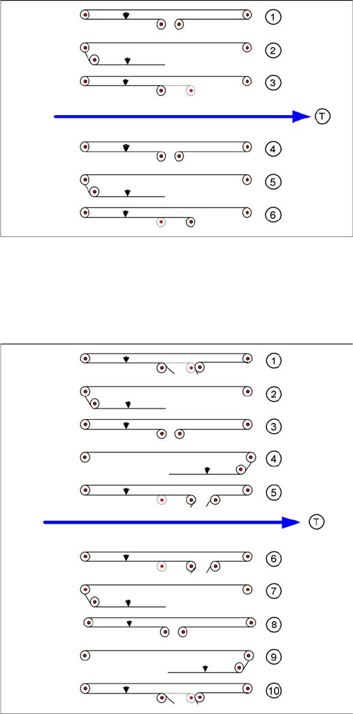
Legend
Measuring points (arrows) and measuring values for con-
veyor belt tensions:
Single conveyor or dual conveyor lane 1
1. Input conveyor: 98 +/-10 Hz
2. Processing area: 64 +/- 6 Hz
3. Output conveyor: 100 +/- 10 Hz
Dual conveyor lane 2
1. Input conveyor: 98 +/- 10 Hz
2. Processing area: 69 +/- 7 Hz
3. Output conveyor: 84 +/- 8 Hz
Width Adjustment
▪ Width adjustment Limit switch, 24 +/- 2 Hz
Legend
Measuring points (arrow) and values for conveyor belt
tensions:
Single conveyor or dual conveyor, track 1
1. Input conveyor: 102 +/-10 Hz
2. Processing area 1: 66 +/- 7 Hz
3. Intermediate conveyor: 94 +/- 9 Hz
4. Processing area 2: 66 +/- 7 Hz
5. Output conveyor: 144 +/- 14 Hz
Dual conveyor, track 2
1. Input conveyor: 144 +/- 14 Hz
2. Processing area 1: 66 +/- 7 Hz
3. Intermediate conveyor: 94 +/- 9 Hz
4. Processing area 2: 66 +/- 7 Hz
5. Output conveyor: 102 +/- 10 Hz
Width adjustment
▪ Width adjustment: 30 +/- 2 Hz
12 Modular Conveyor
12.1 Functions 12.1.14 Measuring Points and Belt Tensions for D4/D4i Conveyor
218 Student Guide SIPLACE D-Series (FSE)
12.1.14
12.1.14 Measuring Points and Belt Tensions for D4/D4i Conveyor
Measuring Points and Belt Tensions for D4/D4i Conveyor
12.1.15
12.1.15 Overview of Flexible Single Conveyor
Overview of Flexible Single Conveyor
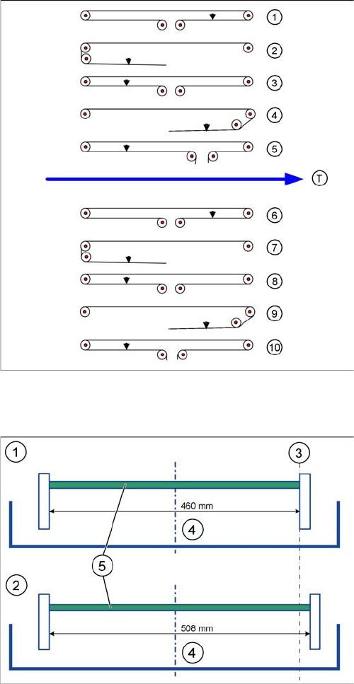
Legend
Measuring points (arrows) and measuring values for con-
veyor belt tensions:
Single conveyor or dual conveyor lane 1
1. Input conveyor: 90 +/- 9 Hz
2. Processing area 1: 72 +/- 7 Hz
3. Intermediate conveyor: 144 +/- 14 Hz
4. Processing area 2: 90 +/- 9 Hz
5. Output conveyor: 90 +/- 9 Hz
Dual conveyor lane 2
1. Input conveyor: 90 +/- 9 Hz
2. Processing area 1: 72 +/- 7 Hz
3. Intermediate conveyor: 115 +/- 12 Hz
4. Processing area 2: 90 +/- 9 Hz
5. Output conveyor: 90 +/- 9 Hz
Width adjustment
▪ Width adjustment Limit switch, 24 +/- 2 Hz
Width of single conveyor
Legend
1. Single conveyor "Standard", max. width 1 x 460 mm
2. Single conveyor "excess width", max. width 1 x 508
mm
3. Fixed conveyor side on right
4. Lane 1
5. Board