00195440-05-SG_D-Series_FSE-EN.pdf - 第22页
2 Operational Safety 2.5 ESD Guidelines 2.4.2 Safety and signaling circuit 22 Student Guide SIPLACE D-Series (FSE)
2 Operational Safety
2.4.2 Safety and signaling circuit 2.5 ESD Guidelines
Student Guide SIPLACE D-Series (FSE) 21
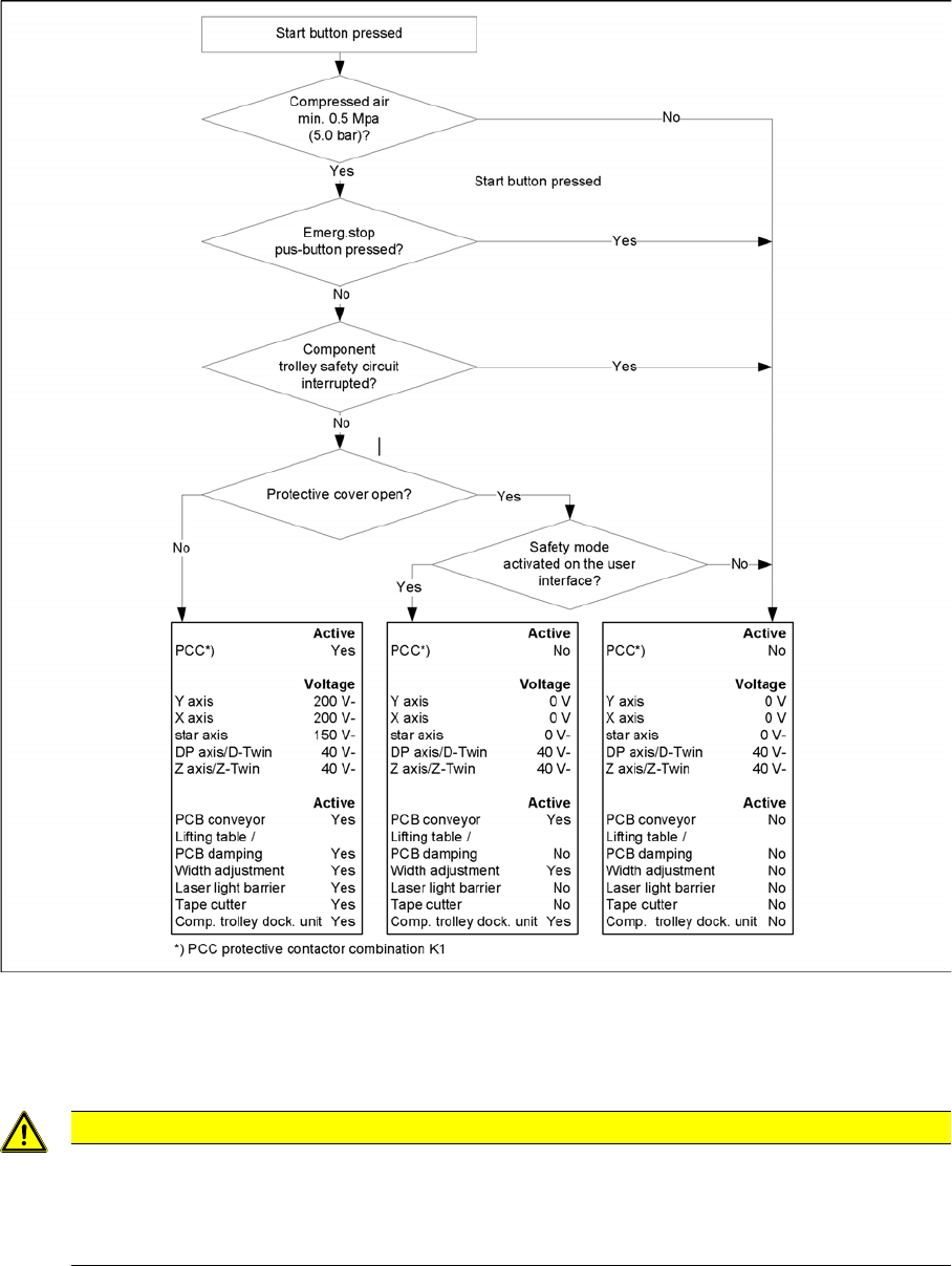
– 40 VDC operating voltage is switched to the component trolleys.
– 24 VDC operating voltage is switched to the empty tape cutters.
– The PCB conveyor control receives the enable signal for the PCB clamping, the PCB stopper
and the lifting table control.
The machine is then ready for use.
2.4.2.2
2.4.2.2 Safety Loops
Safety Loops
Safety loops
2.5
2.5 ESD Guidelines
ESD Guidelines
CAUTION
See operating manual
The ESD guidelines apply for all work to and with the electronic assemblies of your own and
the training machine. For more details about the ESD guidelines, refer to the operating manual
for the relevant SIPLACE machine.
2 Operational Safety
2.5 ESD Guidelines 2.4.2 Safety and signaling circuit
22 Student Guide SIPLACE D-Series (FSE)
3 Overview
3.1.1 Specifications 3.1 General
Student Guide SIPLACE D-Series (FSE) 23
3
3 Overview
Overview
See also
16.6 SIPLACE Vision - Sensor Overview [ ➙ 279]
3.1
3.1 General
General
The high-speed SIPLACE D4/D4i placement machine combines high placement performance with ac-
curacy and flexibility. The machines use the Collect&Place placement method.
The SIPLACE D4/D4i placement machine is equipped with four gantries, for fast and accurate position-
ing along the X and Y axes.
Each gantry has a 12-segment C&P head (C&P12). Each placement area is served by two gantries:
Placement area 1 Gantries 1 and 4
Placement area 2 Gantries 2 and 3
SIPLACE D4/D4i Overview
The components are optically centered with the help of a digital Vision module. Two different component
cameras are available for the placement heads: a standard camera and a high-resolution component
camera.
A five-segment PCB conveyor, consisting of input conveyor, processing conveyor 1, intermediate con-
veyor, processing conveyor 2 and output conveyor, transports the components to the processing posi-
tions. PCB transport can be performed with a single or flexible dual conveyor (with stationary side either
on the left or right). A PCB camera is used to optically center the boards.
3.1.1
3.1.1 Specifications
Specifications
3.1.1.1
3.1.1.1 SIPLACE D4/D4i Specifications – Excerpt
SIPLACE D4/D4i Specifications – Excerpt
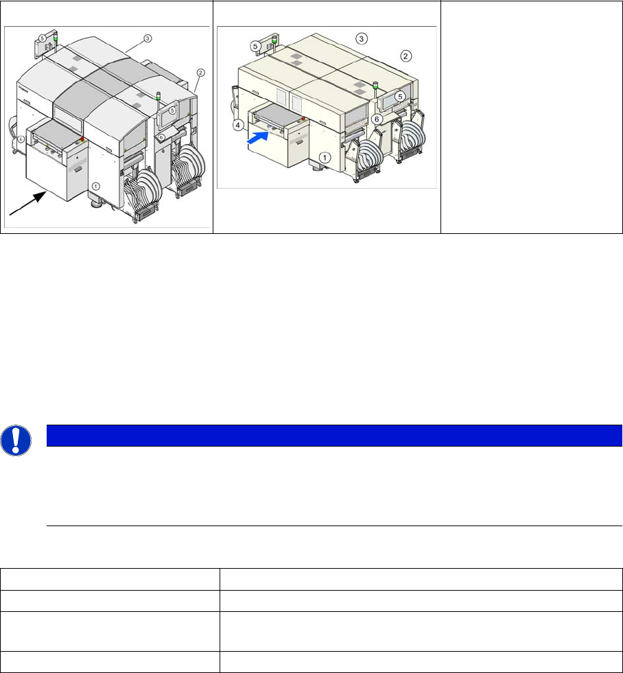
SIPLACE D4 SIPLACE D4i
Legend
1. Sector 1
2. Sector 2
3. Sector 3
4. Sector 4
5. Monitor
6. Keyboard
NOTICE
D/Di-series training CD and download center
The specification for all machine types can be found on the training CD or in the download cent-
er of your SIPLACE user group. You will also find operating manuals, maintenance instructions
and other documentation there.
Types of placement head 12-segment Collect&Place head (C&P12)
Number of gantries 4
Placement performance (bench-
mark test)
60,000 components/h with SC/MC 602
66,000 components/h with SC/MC 603 ~ 605
Placement positions 3,500 / gantry