00195440-05-SG_D-Series_FSE-EN.pdf - 第223页
12 Modular Conveyor 12.3.1 Setting the Fixed Conveyor Side (Single and Dual Conveyo r) 12.3 Conveyor Settings Student Guide SIPLACE D-Series (FSE) 223 ► Loosen the lockscrew(s) (4) and use a screwdriver t o push t he hex…
12 Modular Conveyor
12.3 Conveyor Settings 12.3.1 Setting the Fixed Conveyor Side (Single and Dual Conveyor)
222 Student Guide SIPLACE D-Series (FSE)
► The conveyor sides of the 2nd conveyor lane (right side fixed (lane 1 left side fixed)) are moved to
the limits.
► The SITEST SW ask for connecting the lifting tables.
Widening the board conveyor (from its standard width) allows you to use boards up to 380 mm wide.
If the PCB conveyor is switched from the mode "extra wide" to the mode "widened", this means that D/
Di-series machine can place boards up to a width of approx. 400 mm (D3: approx. 420 mm).
Setting the "fixed conveyor side" in SIPLACE D/Di-Series
Connecting the Dual Conveyor Lifting Tables
► Remove the lifting table plate on conveyor lane 2 in PA1 and on lane 1 in PA2.
NOTICE
Cause of Hazard
The fixed conveyor side should be adjusted only with the SITEST software and the width ad-
justment devices. This ensures that the conveyor runs straight.
NOTICE
This option is only a mechanical function when you use the dual conveyor as a single conveyor.
The two lifting tables move parallel when they are connected.
12 Modular Conveyor
12.3.1 Setting the Fixed Conveyor Side (Single and Dual Conveyor) 12.3 Conveyor Settings
Student Guide SIPLACE D-Series (FSE) 223
► Loosen the lockscrew(s) (4) and use a screwdriver to push the hexagonal circlip over the shaft on
lifting table 1.
► Do this for lifting tables in all placement areas. (lifting tables in the PA’s 180° turned.)
► Configure the new conveyor mode in SIPLACE Pro
To (3): Converting the Single Conveyor Mode Back to Flexible Dual Conveyor Mode
► Select the SITEST conveyor menu "Option and configuration" and then click on Widen conveyor to
set the standard conveyor mode.
► The flexible conveyor side of conveyor 1 (right side fixed (track 1 left side fix)) is moved to a small
conveyor width.
► The SITEST SW ask to disconnect the lifting tables - Do so-.
► The SITEST SW will now use the conveyor control SW to move the fixed side of conveyor 2 (right
side is fixed (lane 1 left side fixed)) back to its standard position. Check the distances between the
two fixed conveyor lanes.
► Now adjust conveyor width of both tracks to desired values.
To (2): Setting the Fixed Conveyor Side for "Extra Wide" Mode
This mode is set in the menu Change position of fixed rail in the software.
The default positions for the fixed conveyor side (s) are predefined.
► Select Option and configuration from the SITEST conveyor menu and then click on Change position
of fixed rail, to set the mode "extra wide".
► The fixed conveyor side TSP 2 (right side fixed (lane 1 left side fixed) remains in its position.
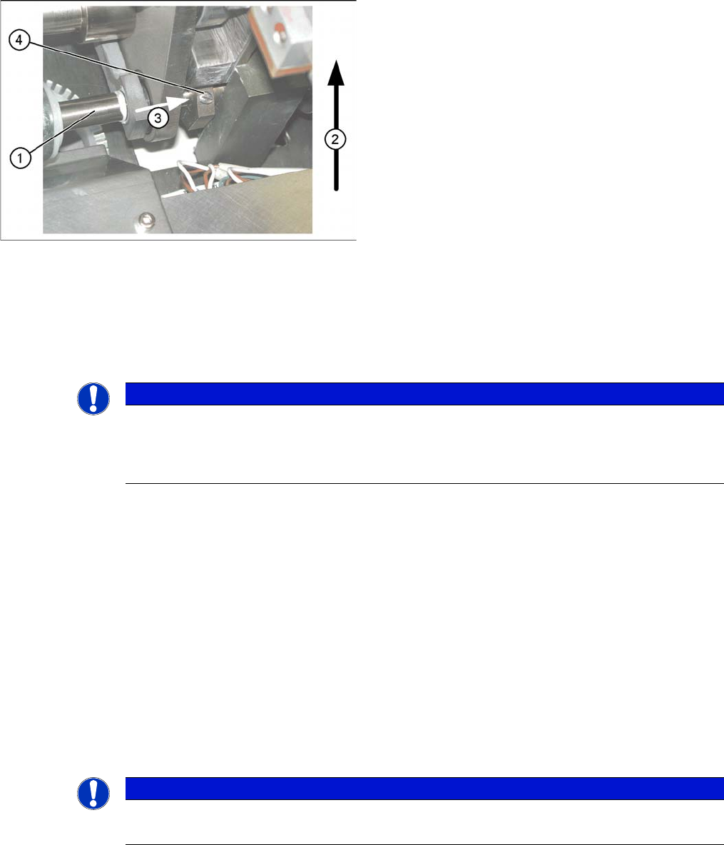
Lifting table
▪ The drive shaft (1) is connected to the piston rod of
the pneumatic cylinder. This shaft couple the second
lifting table of the dual conveyor. The lifting table drive
shaft also has an additional rod with a hexagonal cir-
clip. They secure the sleeve shaft in the desired posi-
tion.
▪ Direction of transport (2)
▪ Direction (3) in which the hollow shaft from lifting ta-
ble 2 (1 in PA 2) is to be moved to lifting table 1 (2 in
PA 2).
▪ Lock screws (4)
NOTICE
When converting the dual conveyor to a single conveyor (flexible dual conveyor, connect the
lifting tables when requested to do so by SITEST (we recommend doing this without com-
pressed air supply to the lifting table).
This function is supported by SIPLACE Pro.
NOTICE
Cause of Hazard
This mode is possible for D/Di-series machines with single or dual conveyors.
12 Modular Conveyor
12.3 Conveyor Settings 12.3.1 Setting the Fixed Conveyor Side (Single and Dual Conveyor)
224 Student Guide SIPLACE D-Series (FSE)
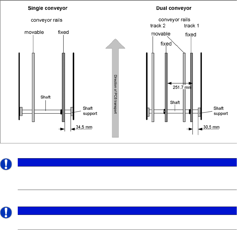
► The fixed conveyor side TSP lane 1 (right side fixed (lane 2 left side fixed) is moved 34 mm outwards.
The flexible conveyor side TSP lane 2 (lane 1 left fixed) can now be set to accommodate boards
which are wider than 216 mm (242 mm).
12.3.1.2
12.3.1.2 Setting the Fixed Conveyor Side (Single and Dual Conveyor)
Setting the Fixed Conveyor Side (Single and Dual Conveyor)
Moving the fixed conveyor side of lane 2 (D1/D1i/D2/D2i)
CAUTION
Cause of Hazard
The end stoppers between the gantries need to be replaced with thinner stoppers, otherwise
you will not be able to perform placement on the fixed side, parallel to the pickup process in the
2nd gantry.
The lubrication nipples in the Y guidance slider are to be replaced with socket-head screws,
otherwise these could be damaged by a gantry crash.
CAUTION
Cause of Hazard
After the conversion, you need to measure or calibrate the PCB reference corner and the con-
veyor sides and then save these values in the machine data.
NOTICE
Cause of Hazard
The setting values for the fixed conveyor side must be checked after the conveyor side fixation
is released. If these values are not correct for the single or dual conveyor, the placement refer-
ence corner could be displaced. In turn, this leads to fiducial recognition errors.