00195440-05-SG_D-Series_FSE-EN.pdf - 第225页
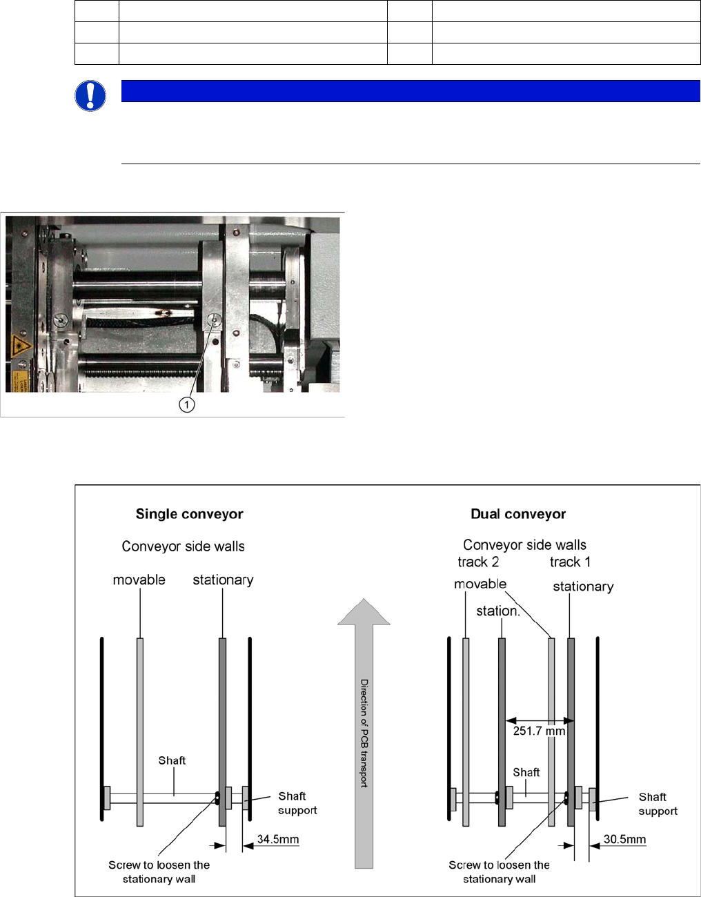
12 Modular Conveyor 12.3.1 Setting the Fixed Conveyor Side (Single and Dual Conveyo r) 12.3 Conveyor Settings Student Guide SIPLACE D-Series (FSE) 225 Legend Procedure: ► Check the measurements . (See followin g diagram)…
12 Modular Conveyor
12.3 Conveyor Settings 12.3.1 Setting the Fixed Conveyor Side (Single and Dual Conveyor)
224 Student Guide SIPLACE D-Series (FSE)
► The fixed conveyor side TSP lane 1 (right side fixed (lane 2 left side fixed) is moved 34 mm outwards.
The flexible conveyor side TSP lane 2 (lane 1 left fixed) can now be set to accommodate boards
which are wider than 216 mm (242 mm).
12.3.1.2
12.3.1.2 Setting the Fixed Conveyor Side (Single and Dual Conveyor)
Setting the Fixed Conveyor Side (Single and Dual Conveyor)
Moving the fixed conveyor side of lane 2 (D1/D1i/D2/D2i)
CAUTION
Cause of Hazard
The end stoppers between the gantries need to be replaced with thinner stoppers, otherwise
you will not be able to perform placement on the fixed side, parallel to the pickup process in the
2nd gantry.
The lubrication nipples in the Y guidance slider are to be replaced with socket-head screws,
otherwise these could be damaged by a gantry crash.
CAUTION
Cause of Hazard
After the conversion, you need to measure or calibrate the PCB reference corner and the con-
veyor sides and then save these values in the machine data.
NOTICE
Cause of Hazard
The setting values for the fixed conveyor side must be checked after the conveyor side fixation
is released. If these values are not correct for the single or dual conveyor, the placement refer-
ence corner could be displaced. In turn, this leads to fiducial recognition errors.
12 Modular Conveyor
12.3.1 Setting the Fixed Conveyor Side (Single and Dual Conveyor) 12.3 Conveyor Settings
Student Guide SIPLACE D-Series (FSE) 225
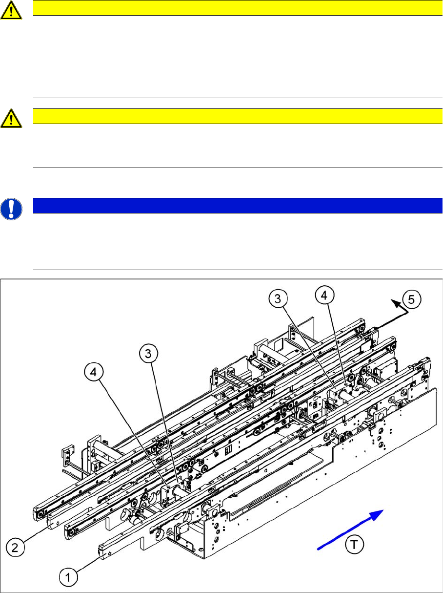
Legend
Procedure:
► Check the measurements . (See following diagram).
Setting the "fixed conveyor side"
► Insert the spring and tighten the screw fastening the brake.
(1) Fixed side - conveyor lane 1 (2) Fixed side - conveyor lane 2
(3) Side flange with grub screw (4) Fastening screw
(5) Fixed side - conveyor lane 2 - moving (T) Transport direction
NOTICE
Cause of Hazard
You do not normally need to adjust the fixed side. One exception is when service work involves
prior movement of the fixed conveyor side.
Modular conveyor detail
► Loosen the fastening screw (1) on the side flange.
► This fastening screw (1) has a socket-head grub
screw inside which needs to be loosened slightly - do
not unscrew completely!
► Remove the fastening screw (1). Watch the spring in-
side.
12 Modular Conveyor
12.3 Conveyor Settings 12.3.2 Conveyor Control
226 Student Guide SIPLACE D-Series (FSE)
► First, fasten the side flange with the screw and then check the measurements on both sides. The two
conveyor sides must run parallel to one another.
► Fasten the second side flange with the screw and then check the measurements again.
► Check the positioning again by moving the PCB conveyor to 216 mm and then move the test board
into the PCB conveyor. The board needs to be moved through the entire conveyor.
12.3.2
12.3.2 Conveyor Control
Conveyor Control
12.3.2.1
12.3.2.1 TSP 201
TSP 201
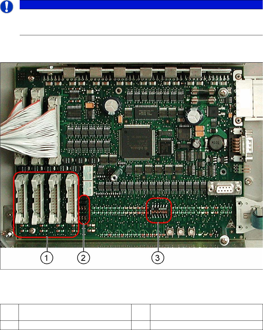
Overview
TSP 201
Legend
NOTICE
Cause of Hazard
The TSP201 conveyor control is used in D1/D1i and D2/D2i machines, while TSP301 conveyor
control is used in D3 and D4/D4i machines.
1 PCB handling (predecessor /successor
stations)
3 DIP switch for single / dual conveyors
2 Jumper for SIEMENS / SMEMA option