00195440-05-SG_D-Series_FSE-EN.pdf - 第226页
12 Modular Conveyor 12.3 Conveyor Settings 12.3.2 Conveyor Control 226 Student Guide SIPLACE D-Series (FSE) ► First, fasten the side f lange with the scre w and th en check the measurements on both sides. The two conveyo…
12 Modular Conveyor
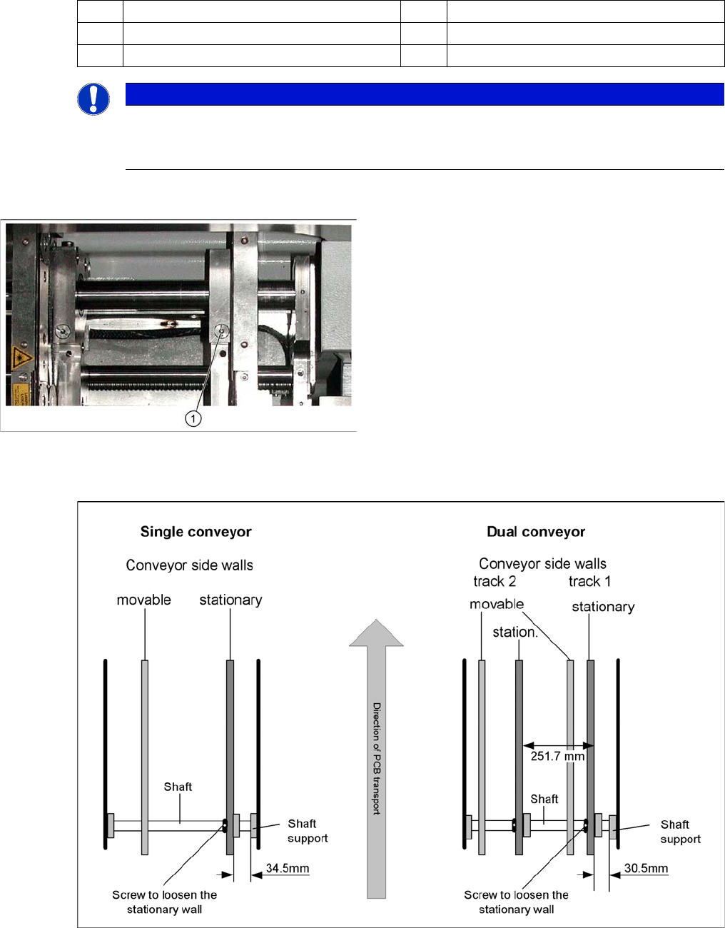
12.3.1 Setting the Fixed Conveyor Side (Single and Dual Conveyor) 12.3 Conveyor Settings
Student Guide SIPLACE D-Series (FSE) 225
Legend
Procedure:
► Check the measurements . (See following diagram).
Setting the "fixed conveyor side"
► Insert the spring and tighten the screw fastening the brake.
(1) Fixed side - conveyor lane 1 (2) Fixed side - conveyor lane 2
(3) Side flange with grub screw (4) Fastening screw
(5) Fixed side - conveyor lane 2 - moving (T) Transport direction
NOTICE
Cause of Hazard
You do not normally need to adjust the fixed side. One exception is when service work involves
prior movement of the fixed conveyor side.
Modular conveyor detail
► Loosen the fastening screw (1) on the side flange.
► This fastening screw (1) has a socket-head grub
screw inside which needs to be loosened slightly - do
not unscrew completely!
► Remove the fastening screw (1). Watch the spring in-
side.
12 Modular Conveyor
12.3 Conveyor Settings 12.3.2 Conveyor Control
226 Student Guide SIPLACE D-Series (FSE)
► First, fasten the side flange with the screw and then check the measurements on both sides. The two
conveyor sides must run parallel to one another.
► Fasten the second side flange with the screw and then check the measurements again.
► Check the positioning again by moving the PCB conveyor to 216 mm and then move the test board
into the PCB conveyor. The board needs to be moved through the entire conveyor.
12.3.2
12.3.2 Conveyor Control
Conveyor Control
12.3.2.1
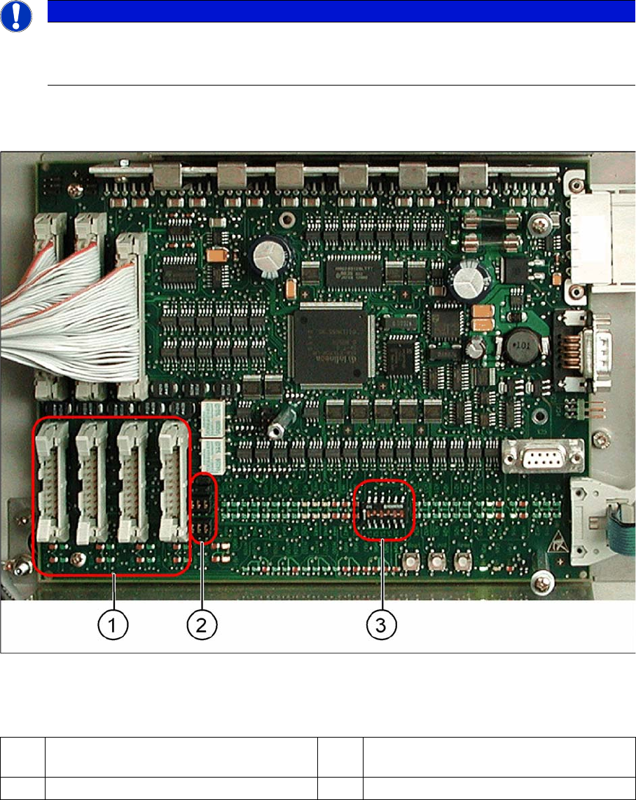
12.3.2.1 TSP 201
TSP 201
Overview
TSP 201
Legend
NOTICE
Cause of Hazard
The TSP201 conveyor control is used in D1/D1i and D2/D2i machines, while TSP301 conveyor
control is used in D3 and D4/D4i machines.
1 PCB handling (predecessor /successor
stations)
3 DIP switch for single / dual conveyors
2 Jumper for SIEMENS / SMEMA option
12 Modular Conveyor
12.3.2 Conveyor Control 12.3 Conveyor Settings
Student Guide SIPLACE D-Series (FSE) 227
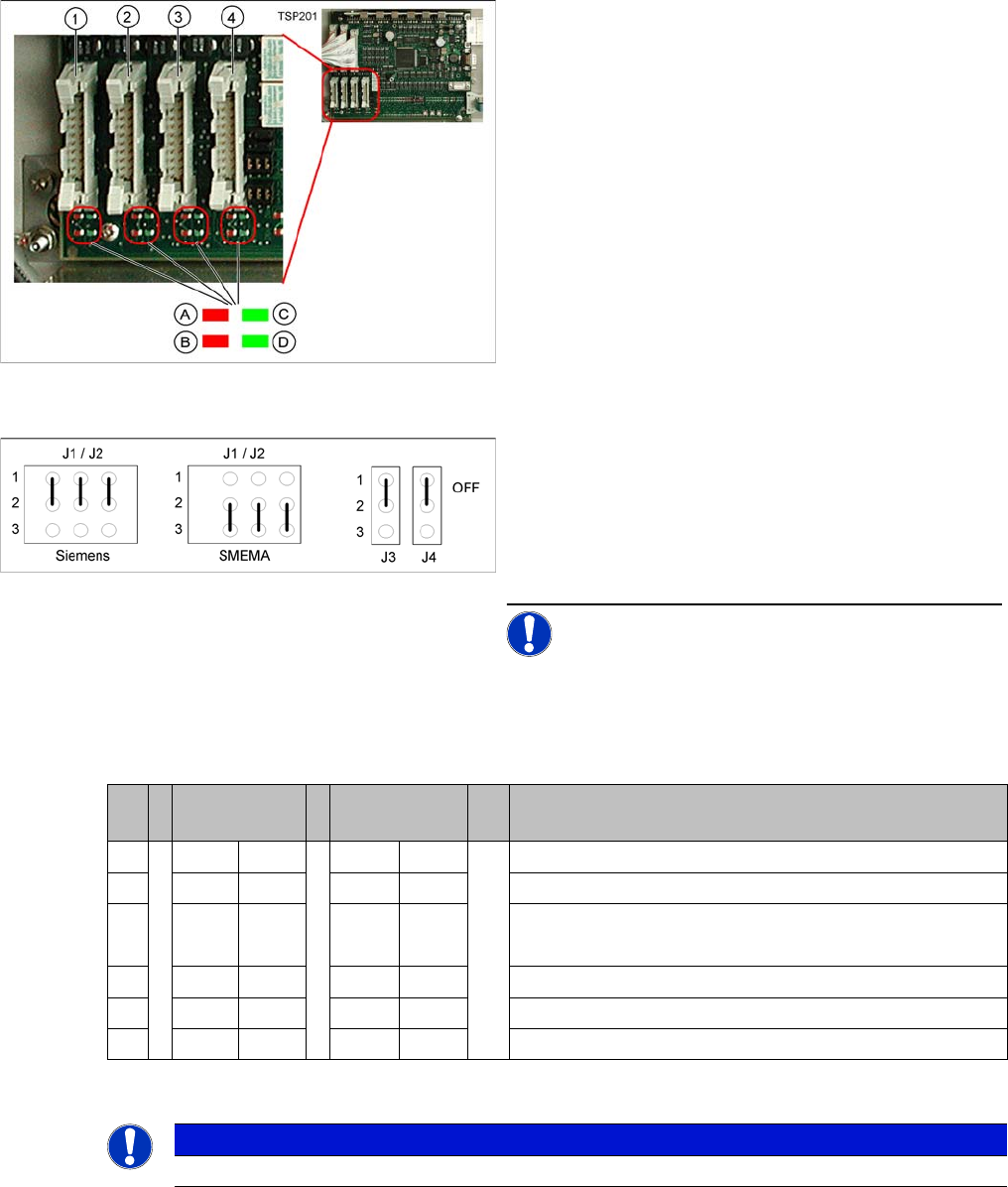
PCB Handling - Predecessor and Successor Station
SIEMENS / SMEMA
Single / Dual Conveyor
DIP switch S1 on TSP201
LEDs on the TSP201
Legend
1. X1 – PCB handling – predecessor station lane 1
2. X2 – PCB handling – successor station lane 1
3. X4 – PCB handling – predecessor station lane 2
4. X5 – PCB handling – successor station lane 2
Connector and interface status display
▪ A = Received
▪ B = Permitted
▪ C = Transmitted
▪ D = Requested
Jumper J1, J2 "successor/predecessor station" at TSP
201
Legend
▪ J1 predecessor station
▪ J2 successor station
▪ J3/J4 interference loop (emergency stop on produc-
tivity lift switches the placement machine off)
NOTICE! Jumpers J1 and J2 can be set inde-
pendently of one another, at SIEMENS or SMEMA.
S Single con-
veyor
Dual conveyor Comments
1OFF ON OFF = single conveyor, ON = dual conveyor
2ON ONStation type (always ON)
3OFF OFF OFF = clamping sensor disabled (with adj unit)
ON = without adj unit
4ON ONOFF = 125 Kbit/s (S27), ON = 1 Mbit/s (D1/D1i/D2)/D2i
5oo oo CAN terminating resistor, OFF for D1/D1i, ON for D2/D2i
6OFF OFF not used
NOTICE
See also the label on the TSP201 cover.