00195440-05-SG_D-Series_FSE-EN.pdf - 第228页
12 Modular Conveyor 12.3 Conveyor Settings 12.3.2 Conveyor Control 228 Student Guide SIPLACE D-Series (FSE) 12.3.2.2 1 2 . 3 . 2 . 2 T S P 3 0 1 TSP 301 Jumper Settings for TSP 301 DIL switch S4 at TSP 301 * Switches 1 a…
12 Modular Conveyor
12.3.2 Conveyor Control 12.3 Conveyor Settings
Student Guide SIPLACE D-Series (FSE) 227
PCB Handling - Predecessor and Successor Station
SIEMENS / SMEMA
Single / Dual Conveyor
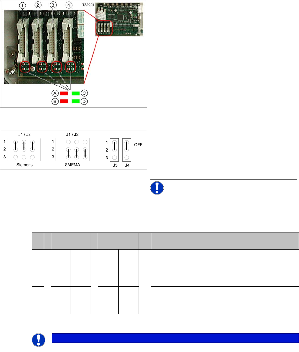
DIP switch S1 on TSP201
LEDs on the TSP201
Legend
1. X1 – PCB handling – predecessor station lane 1
2. X2 – PCB handling – successor station lane 1
3. X4 – PCB handling – predecessor station lane 2
4. X5 – PCB handling – successor station lane 2
Connector and interface status display
▪ A = Received
▪ B = Permitted
▪ C = Transmitted
▪ D = Requested
Jumper J1, J2 "successor/predecessor station" at TSP
201
Legend
▪ J1 predecessor station
▪ J2 successor station
▪ J3/J4 interference loop (emergency stop on produc-
tivity lift switches the placement machine off)
NOTICE! Jumpers J1 and J2 can be set inde-
pendently of one another, at SIEMENS or SMEMA.
S Single con-
veyor
Dual conveyor Comments
1OFF ON OFF = single conveyor, ON = dual conveyor
2ON ONStation type (always ON)
3OFF OFF OFF = clamping sensor disabled (with adj unit)
ON = without adj unit
4ON ONOFF = 125 Kbit/s (S27), ON = 1 Mbit/s (D1/D1i/D2)/D2i
5oo oo CAN terminating resistor, OFF for D1/D1i, ON for D2/D2i
6OFF OFF not used
NOTICE
See also the label on the TSP201 cover.
12 Modular Conveyor
12.3 Conveyor Settings 12.3.2 Conveyor Control
228 Student Guide SIPLACE D-Series (FSE)
12.3.2.2
12.3.2.2 TSP 301
TSP 301
Jumper Settings for TSP 301
DIL switch S4 at TSP 301
* Switches 1 and 2 set the hardware ID 5 for D4/D4i machines and hardware ID 6 for X4I, X series, HF
and D3.ID 7 for Width Adjustment Unit
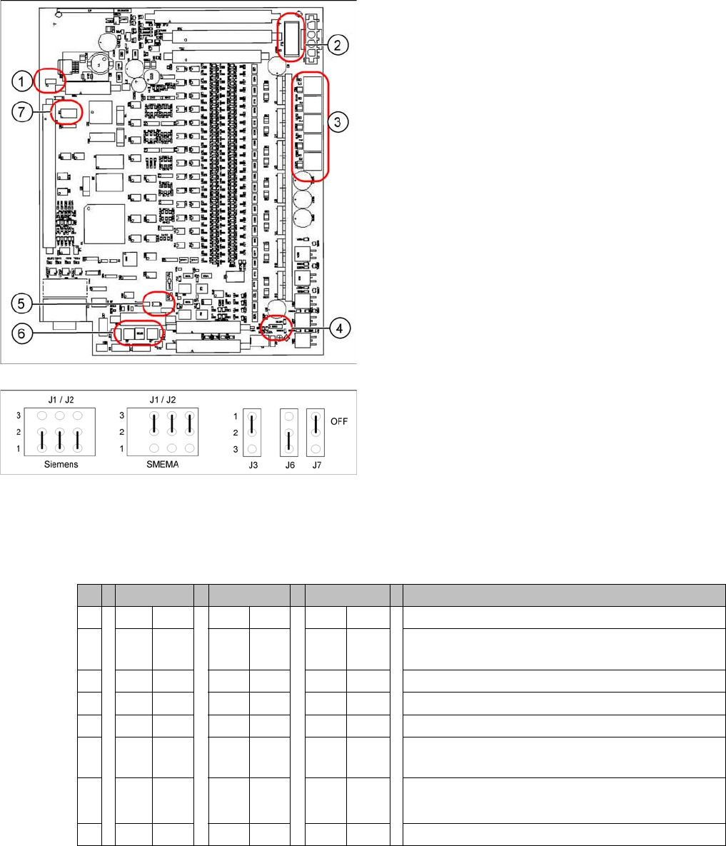
Legend
1. J7 CAN bus 1 terminating resistor
2. F6 Main Fuse TSP 301
3. F1 - F5 Fuses for the conveyor motors
4. J3 interference loop
5. J6 CAN bus 2 terminating resistor (not used)
6. J2, J1 successor/predecessor station
7. S4 DIL switch
Jumper J1, J2 "downstream/upstream station" at TSP
301
Legend
▪ J1 predecessor station
▪ J2 successor station
▪ J3 interference loop (EMERGENCY STOP on pro-
ductivity lift also switches the placement machine off)
▪ J6 CAN bus 2 terminating resistor (not used)
▪ J7 CAN bus 1 terminating resistor
S X4I D4 X/D3/HF Comments
1* ON ON ON ON
2* OFF ON OFF ON = SIPLACE D4/D4i, OFF: SIPLACE X, HF, D3,
X4I
3 OFF OFF OFF OFF= clamping sensor is no longer used
4ONONOFF OFFONON = quad lane, OFF: default conveyor
5 OFF OFF OFF Not in use
6 OFF ON OFF OFF ON OFF: Default conveyor, ON: quad lane (conveyor
edges fixed on outside)
7 OFF OFF OFF OFF: With width adj unit
ON: Without width adj. unit
8 OFF OFF OFF Not in use
12 Modular Conveyor
12.3.2 Conveyor Control 12.3 Conveyor Settings
Student Guide SIPLACE D-Series (FSE) 229
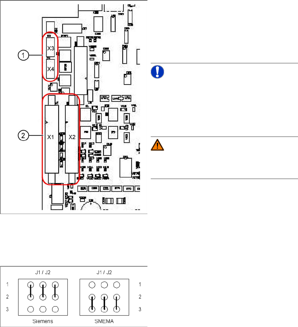
Conveyor Control TSP 301 with Siemens Interface
TSP 301 SMEMA --> Siemens
Legend
1. 10-pin plug for SMEMA interface
X3: upstream station
X4: successor station
2. Connection for Siemens interface
X1: upstream station
X2: successor station
NOTICE! Standard / Option
The SMEMA interface is a standard on all X machines
and the Siemens interface is optional.
The Siemens interface is a standard on all D/Di machines
and the SMEMA interface is optional. The SMEMA inter-
face requires an adapter when used with the D1/2/4/D1i/
D2i/D4i.
WARNING! Risk of irreparable damage to the
TSP board!
The 10 pin Locking clip plug of SMEMA connections must
be disconnected from the TSP 301!
Application: no modification.
Following modification are necessary for using the Sie-
mens interface:
► JumperJ1 / J2: need to be moved (see following dia-
gram).
► Disconnect the connector X3 and X4 on the TSP 301!
► Connect the Siemens interface cable on the connec-
tor X1 and X2.
Jumper J1 and J2 (Siemens/SMEMA)