00195440-05-SG_D-Series_FSE-EN.pdf - 第24页
3 Overview 3.1 General 3.1.1 Specifications 24 Student Guide SIPLACE D-Series (FSE) Range of compon ents 0.6 x 0.3 mm 2 (0201) to 18.7 x 18.7 mm 2 Max. component height 6 mm Placement accuracy / angle accu - racy Camera …
3 Overview
3.1.1 Specifications 3.1 General
Student Guide SIPLACE D-Series (FSE) 23
3
3 Overview
Overview
See also
16.6 SIPLACE Vision - Sensor Overview [ ➙ 279]
3.1
3.1 General
General
The high-speed SIPLACE D4/D4i placement machine combines high placement performance with ac-
curacy and flexibility. The machines use the Collect&Place placement method.
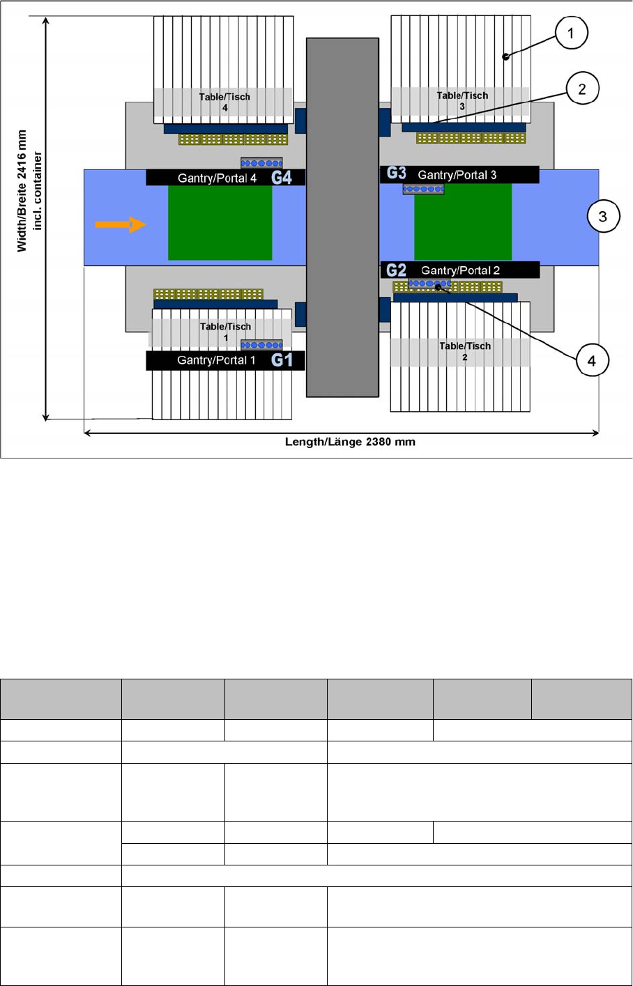
The SIPLACE D4/D4i placement machine is equipped with four gantries, for fast and accurate position-
ing along the X and Y axes.
Each gantry has a 12-segment C&P head (C&P12). Each placement area is served by two gantries:
Placement area 1 Gantries 1 and 4
Placement area 2 Gantries 2 and 3
SIPLACE D4/D4i Overview
The components are optically centered with the help of a digital Vision module. Two different component
cameras are available for the placement heads: a standard camera and a high-resolution component
camera.
A five-segment PCB conveyor, consisting of input conveyor, processing conveyor 1, intermediate con-
veyor, processing conveyor 2 and output conveyor, transports the components to the processing posi-
tions. PCB transport can be performed with a single or flexible dual conveyor (with stationary side either
on the left or right). A PCB camera is used to optically center the boards.
3.1.1
3.1.1 Specifications
Specifications
3.1.1.1
3.1.1.1 SIPLACE D4/D4i Specifications – Excerpt
SIPLACE D4/D4i Specifications – Excerpt
SIPLACE D4 SIPLACE D4i
Legend
1. Sector 1
2. Sector 2
3. Sector 3
4. Sector 4
5. Monitor
6. Keyboard
NOTICE
D/Di-series training CD and download center
The specification for all machine types can be found on the training CD or in the download cent-
er of your SIPLACE user group. You will also find operating manuals, maintenance instructions
and other documentation there.
Types of placement head 12-segment Collect&Place head (C&P12)
Number of gantries 4
Placement performance (bench-
mark test)
60,000 components/h with SC/MC 602
66,000 components/h with SC/MC 603 ~ 605
Placement positions 3,500 / gantry

3 Overview
3.1 General 3.1.1 Specifications
24 Student Guide SIPLACE D-Series (FSE)
Range of components
0.6 x 0.3 mm
2
(0201) to 18.7 x 18.7 mm
2
Max. component height 6 mm
Placement accuracy / angle accu-
racy
Camera type 28: ± 60 µm, ± 0.5° (3 s), ± 80 µm, ± 0.7° (4 s)
Camera type 29: ± 60 µm, ± 0.5° (3 s), ± 80 µm, ± 0.7° (4 s)
Camera type 30: ± 41 µm, ± 0.4° (3 s), ± 55 µm, ± 0.5° (4 s)
Component feeding 4 component trolleys with tape reel holder and integrated waste
containers (12 locations à 30 mm width per component trolley)
Feeder module types Tape, bulkcase, stick magazines, application-specific OEM feeder
modules, surftape feeder modules (8, 12, 16 mm), waffle pack
trays
Feeding capacity 48 tape feeder modules 3 x 8 mm S (144 tracks)
48 tape feeder modules 2 x 8 mm S (96 tracks)
48 tape feeder modules x 12/16 mm S (48 tracks)
32 tape feeder modules x 24/32 mm S (32 tracks)
PCB format
(LxW)
Single conveyor
50 x 50 mm
2
to 368 x 460 mm
2
50 x 110 mm
2
to 610 x 460 mm
2
(option "Long board")
Width up to 508 mm on request
Dual conveyor
50 x 50 mm
2
to 368 x 216 mm
2
50 x 110 mm
2
to 610 x 216 mm
2
(option "Long board")
Width up to 242 mm on request
Dual conveyor in Single conveyor mode
50 x 50 mm
2
to 368 x 380 mm
2
50 x 110 mm
2
to 610 x 380 mm
2
(option "Long board")
Width up to 430 mm on request
PCB thickness 0.3 to 4.5 mm (thicker PCBs available on request)
3 Overview
3.1.2 SIPLACE D4/D4i Configuration 3.2 Machine Overview Comparison D1/D1i to D4/D4i
Student Guide SIPLACE D-Series (FSE) 25
3.1.2
3.1.2 SIPLACE D4/D4i Configuration
SIPLACE D4/D4i Configuration
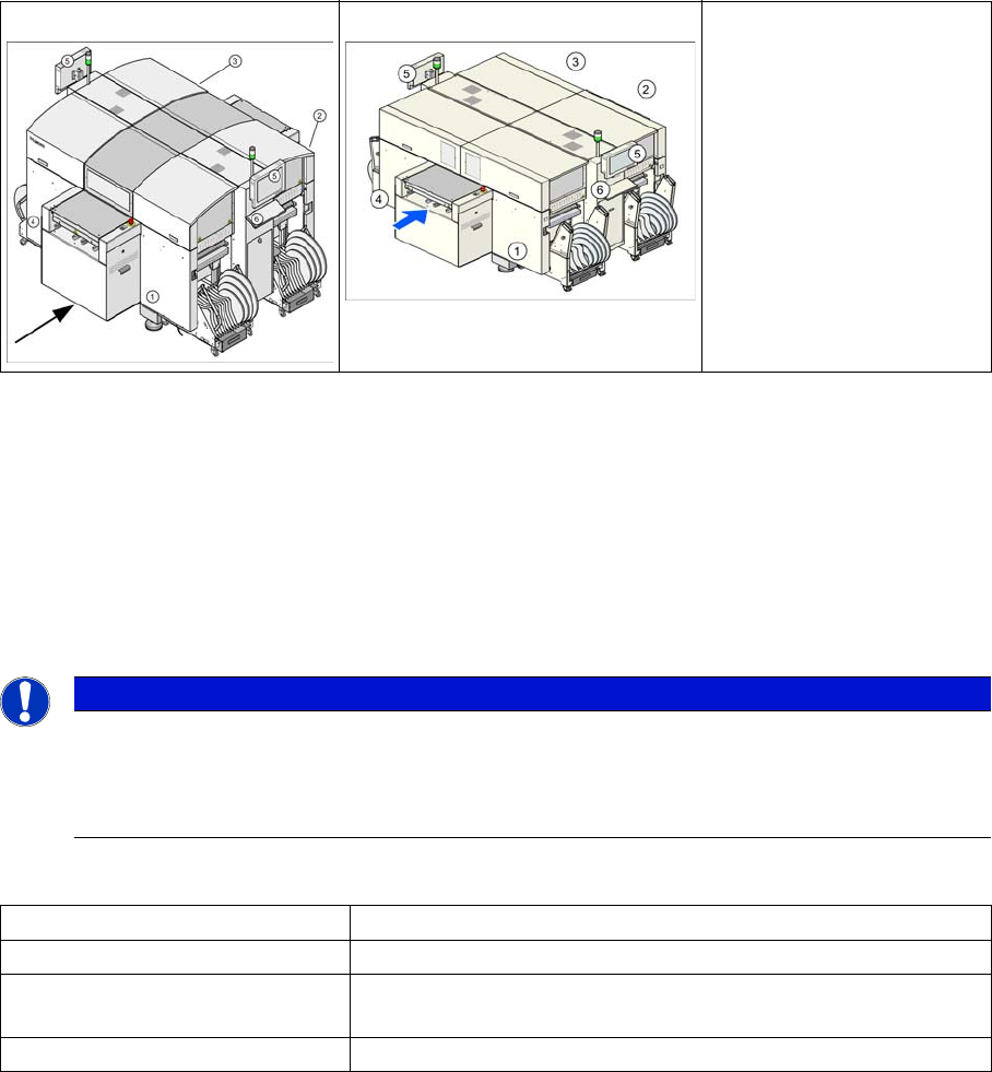
SIPLACE D4/D4i configuration
Legend
1. S-table with S-feeder
2. Reject container for components and nozzles, without sensor for the reject container
3. Single/dual conveyor with stationary side on left or right
4. 4x C&P12
3.2
3.2 Machine Overview Comparison D1/D1i to D4/D4i
Machine Overview Comparison D1/D1i to D4/D4i
Designation D4/D4i D3 D2/D2i D1/D1i D1/D1i single
head
Succeeds HS50/60 ---- S2X FX
Processing areas 21
SMEMA height in-
creases
3 distance
plates (70, 100,
120 mm)
2 distance
plates (70, 100/
120, mm)
3 distance plates (70, 100, 120 mm)
Gantries 432 1
Cast gantry CFK gantry Extended cast gantry
Y drive Linear motor
X-drive Motor with belt
drive
Linear motor Motor with belt drive
Y-motor cooling Through com-
pressed air
supply
Through motor
generating
compressed air
Through compressed air supply