00195440-05-SG_D-Series_FSE-EN.pdf - 第251页
14 SITEST 14.3.5 PCB Mapping 14.3 Calibration Basics Student Guide SIPLACE D-Series (FSE) 251 Position mapping pla te and convey or sid e position for single an d dual con veyor 14.3.5.2 1 4 . 3 . 5 . 2 P r o c e d u r e…
14 SITEST
14.3 Calibration Basics 14.3.5 PCB Mapping
250 Student Guide SIPLACE D-Series (FSE)
14.3.4.3
14.3.4.3 PCB Reference Corner
PCB Reference Corner
► Select gantry 1 or 2.
► Select PCB reference corner position right or PCB reference corner position left (dual conveyor)
► Moves the active gantry with the PCB camera over the reference corner position and switches the
screen display to the PCB camera for checking purposes. The reference corner position is visible in
the camera's field of view. Teach the gantry at the top right edge of the board, so that the PCB ref-
erence corner is in the center of the camera's field of vision.
► This PCB reference corner determines the position coordinates for the PCB position fiducial search
in the machine.
14.3.4.4
14.3.4.4 Pickup Position (Calibrating the Changeover Table)
Pickup Position (Calibrating the Changeover Table)
This calibration step determines the X and Y positions for the changeover tables which, depending on
the type, will be tracks 1-72 or 1-90 or which, depending on the configuration, can be 1-90 (without WPC)
or 61-90 (with WPC). A connected and activated WPC is automatically recognized by the software.
Calibrating the changeover table
14.3.5
14.3.5 PCB Mapping
PCB Mapping
With the PCB mapping the linearity of the X- and Y-guidance for PCB-camera movement is measured
in the placement area. The PCB-camera center the cross fiducials on a high precise glass plate. This
mapping plate has been measured with a measuring device and the dimensions are taken into account
during the mapping procedure.
14.3.5.1
14.3.5.1 Preparation for Mapping
Preparation for Mapping
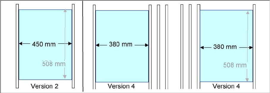
► At the single conveyor the SITEST move the transport sides to 508mm wide the mapping plate is 90
degree turned.
► At dual conveyor the SITEST SW move all the conveyor sides depend of the conveyer which is se-
lected the conveyor for mapping to 450 mm wide the other track to 0mm. This enables you to use
the dual conveyor as single conveyor. The Mapping must be carried out for the maximum conveyor
width.
► To prepare the board and RV mapping procedure, the SITEST SW automatically sets the conveyor
sides, so that the mapping plate fits into the relevant conveyor side.
► The C&P12 must be equipped with nozzle type 956.
► The calibration tools are in the calibration pocket.
14 SITEST
14.3.5 PCB Mapping 14.3 Calibration Basics
Student Guide SIPLACE D-Series (FSE) 251
Position mapping plate and conveyor side position for single and dual conveyor
14.3.5.2
14.3.5.2 Procedure:
Procedure:
► Place the mapping disk or CD-ROM in the station computer and copy the measurement data for this
mapping plate.
► Put the mapping plate in the input conveyor for placement area 1 or in the intermediate conveyor for
placement area 2.
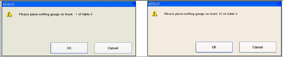
► Now appears the teach menu to teach the fixed PCB corner OK.
► PCB mapping is running.
► Then the gantry axes move the camera up to the start position. The light-colored fiducial cross will
now be centered with the help of a synthetic image.
► This results are set for the nominal coordinates. 40.000 µm in X- respectively Y- direction added for
the next fiducial nominal position.
► The deviation of the structure to this theoretical position is measured.
14 SITEST
14.3 Calibration Basics 14.3.6 Head Mapping (C&P Head)
252 Student Guide SIPLACE D-Series (FSE)
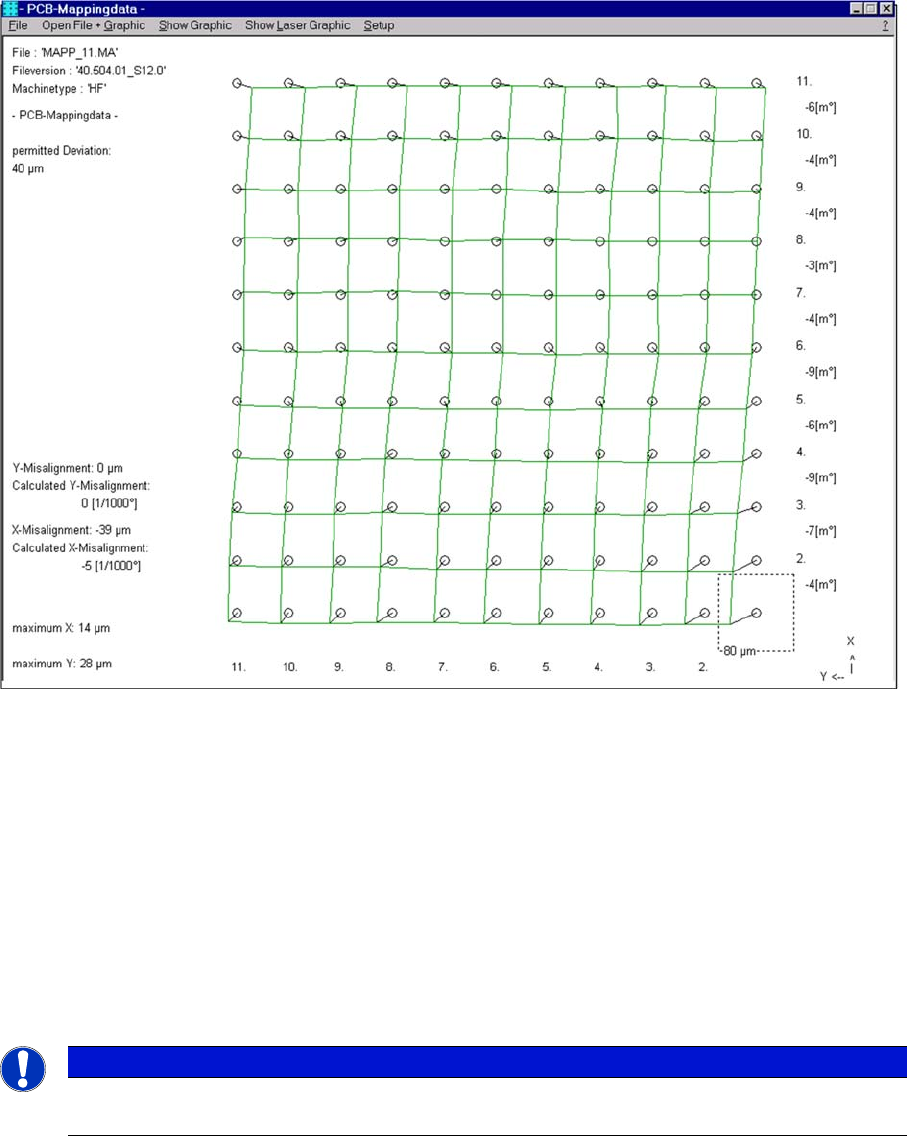
Result of PCB mapping
The results will be saved in the file MAPP_xy.MA (x= gantry number, y= conveyor lane).
14.3.6
14.3.6 Head Mapping (C&P Head)
Head Mapping (C&P Head)
Head mapping measures the linearity of the C&P head X/Y guidance.
The C&P head places the calibration tool precisely on the default positions of the mapping plate. The
PCB-camera measure the placement accuracy of this placements for the whole placement area.
▪ After the PCB mapping the placement head place at the theoretical positions of the PCB-mapping
the calibration tool.
▪ The PCB camera measures the placement accuracy with the help of the 4 calibration tool fiducials
on the calibration tool upper side.
NOTICE
All described automatically calibration steps above, can you do manually step by step under
the sub menus (see chapter 12.1).