00195440-05-SG_D-Series_FSE-EN.pdf - 第26页
3 Overview 3.2 Machine Overview Comparison D1/D 1i to D4/D4i 3.1.2 SIPLACE D 4/D4i C onfiguration 26 Student Guide SIPLACE D-Series (FSE) X-motor cooling Through fan during compo - nent pickup Through ex - haust from C&a…
3 Overview
3.1.2 SIPLACE D4/D4i Configuration 3.2 Machine Overview Comparison D1/D1i to D4/D4i
Student Guide SIPLACE D-Series (FSE) 25
3.1.2
3.1.2 SIPLACE D4/D4i Configuration
SIPLACE D4/D4i Configuration
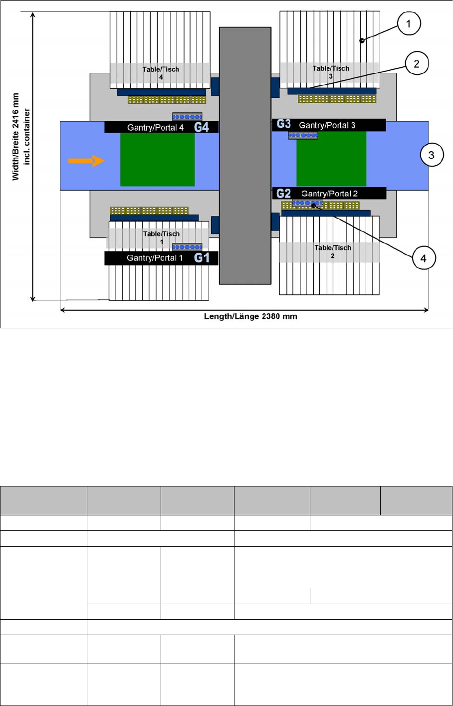
SIPLACE D4/D4i configuration
Legend
1. S-table with S-feeder
2. Reject container for components and nozzles, without sensor for the reject container
3. Single/dual conveyor with stationary side on left or right
4. 4x C&P12
3.2
3.2 Machine Overview Comparison D1/D1i to D4/D4i
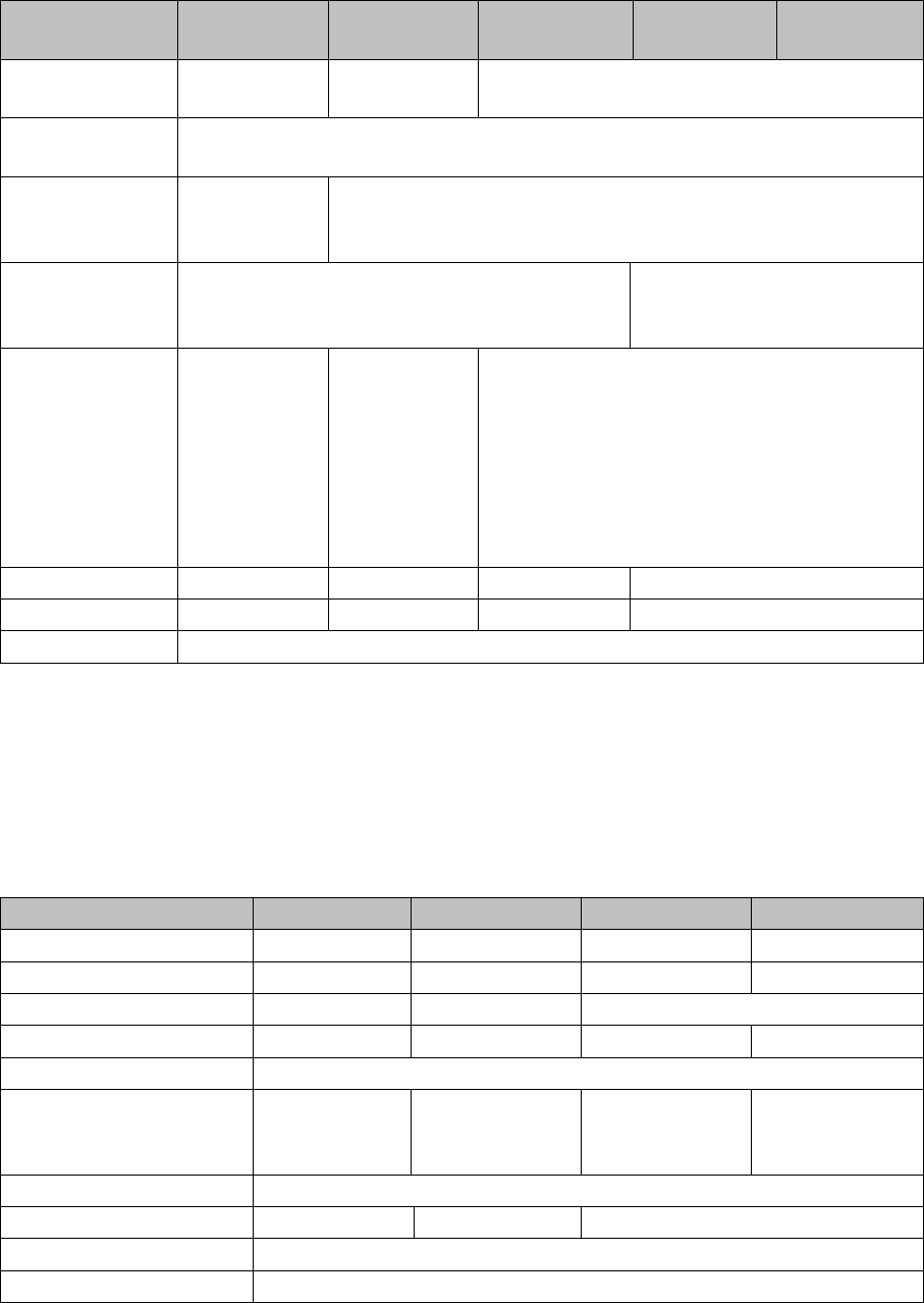
Machine Overview Comparison D1/D1i to D4/D4i
Designation D4/D4i D3 D2/D2i D1/D1i D1/D1i single
head
Succeeds HS50/60 ---- S2X FX
Processing areas 21
SMEMA height in-
creases
3 distance
plates (70, 100,
120 mm)
2 distance
plates (70, 100/
120, mm)
3 distance plates (70, 100, 120 mm)
Gantries 432 1
Cast gantry CFK gantry Extended cast gantry
Y drive Linear motor
X-drive Motor with belt
drive
Linear motor Motor with belt drive
Y-motor cooling Through com-
pressed air
supply
Through motor
generating
compressed air
Through compressed air supply

3 Overview
3.2 Machine Overview Comparison D1/D1i to D4/D4i 3.1.2 SIPLACE D4/D4i Configuration
26 Student Guide SIPLACE D-Series (FSE)
X-motor cooling Through fan
during compo-
nent pickup
Through ex-
haust from
C&P/TWIN
heads
Through fan during component pickup
Platine an der
X-Achse
Gantry head
distributor, ver-
sion 3
Head interface/
adapter
Gantry head distributor, version 3
Platine an der
Y-Achse
Gantry distribu-
tor
Gantry inter-
face
Gantry distributor
Placement head
type
C&P12 C&P12/6 PA1 /
C&P12/6 /
TWIN PA2
C&P12/6 C&P12/6 und
P&P
(= 1 TWIN
segment)
C&P12/6 or
P&P
(= 1 TWIN
segment)
C&P-Version DLM3
Max. component
height
6 mm C&P12: 6 mm
C&P6: 8.5 mm
TWIN: 25 mm
C&P12: 6 mm
C&P6: 8.5 mm
C&P12: 6 mm
C&P6: 8.5 mm
P&P: 19 mm
Conveyor 5-parts 3-parts
Conveyor control TSP 301 TSP 201
For dual conveyor With extension board Without extension board
SC BoxPC (or Sin-
gle BoxPC)
Currently with
computer rack
or box PC
BoxPC (or Single BoxPC)
Basic software SC/MC602 SC/MC603.01 SC/MC603.01
SP1
MC Micro Box PC
+ USB DVD-
LW (or incorpo-
rate into Single
BoxPC)
MC slot PC
(C086) or Box
PC
+ USB DVD-
LW
Micro Box PC
+ USB DVD-LW (or incorporate into Single Box-
PC)
MC operating sys-
tem
602 RMOS/603 WinXP/605
WinXPe
603 WinXP/605 WinXPe
USB hub 7-fold 4-fold 7-fach (od. 4-fach)
Axis controller
rack
2 racks with code switch 1 rack with code switch to standard
Axis controller A364 A363/A364 A364
Pneumatic
changeover table
docking unit
--- YES ---
No. changeover
table positions per
location
1 each STP 2 / STP1
Pos für D2
STP 1 pos D2 or D1
(Pos. D1 35 mm further outside
than D2)
Cutter HS version HF version Neu, verlängerte HS
Changeover table
S feeder
HF version Neu, verbreitert
Kopf-Modularität --- C&P12/6/
TWIN
C&P12/6 C&P12/6 with P&P
Bestückkopf/ Ser-
vo-Teile
No Same as X ma-
chine
C&P and P&P module
Designation D4/D4i D3 D2/D2i D1/D1i D1/D1i single
head
3 Overview
3.3.1 Machine Options 3.3 Possible Options for D/Di-Series Machines
Student Guide SIPLACE D-Series (FSE) 27
** No Coplan ILD 2200 if the machine is running with Single BoxPC system
3.3
3.3 Possible Options for D/Di-Series Machines
Possible Options for D/Di-Series Machines
3.3.1
3.3.1 Machine Options
Machine Options
Hardware - new features for C&P placement head
*) Assembly position at location 2: inside, on conveyor belt
Assembly position at location 4: outside, to make room for the component camera SST36 and the reject
container.
**)-No Coplan ILD 2200 if the machine is running with Single BoxPC system
HM-Teilesatz für
Kopfmontage
No --- Set for D-series
HM-Teilesatz für
Servos und PPW
YES
Kamera-
Modularität
SST28/SST29/
SST30/SST38
SST28/SST29/SST30/SST38 für C&P12
oder SST29/SST30 für C&P6
(also P&P on D1: SST36, optional SST33 und SST 25)
Temperature
compensation I
Both gantries in the placement area (PA) check
the PCB position.
Die LP-Kamera prüft IC/FC-
Kameraposition in definierten
Abständen
Temperature
compensation II
Temperature
sensor at C&P
gantries
Temperatur-
sensoren am
C&P-Portal/
TWIN IC/FC-
Kamera-
position prüfen
in definierten
Abständen
Temperature sensor at C&P gantries
FlipChip camera --- YES --- YES
Coplan ILD 2200 --- YES --- YES/No**
GEM option ---
Designation D4/D4i D3 D2/D2i D1/D1i D1/D1i single
head
Option D4/D4i D3 D2/D2i D1/D1i
Coplan ILD 2200 --- YES --- YES/NO**)
FlipChip camera SST25 --- YES --- YES
MTC2 --- Yes *) ---
WPC4 --- ab SC/MC 605 --- YES
Vacuum pump Possible
DIP module --- YES ---
Not with feeder
cover flap
YES
0201 set Yes, with SST 29 (Di with SST30 with 605.03 SP2)
01005 set From 04/2008 --- From 04/2008
Setup Center YES
Splice detection YES