00195440-05-SG_D-Series_FSE-EN.pdf - 第268页
16 Annex (FSE) 16.3 Calibration Steps and Individual Calibration Functions 268 Student Guide SIPLACE D-Series (FSE) 16.3 1 6 . 3 C a lib r a t io n S t e p s a n d I n d iv id u a l C a lib r a t io n F u n c t io n s Ca…
16 Annex (FSE)
16.2 Overview of Settings and Calibration Work
Student Guide SIPLACE D-Series (FSE) 267
calibrations
from the left to the right
reasons for
calibrations
Zero point corr. star-axis C&P-head
Zero point corr. Z-/ D-axis and basic
force sensor parameter TWIN-head
Calibrate MA-zero point both gantries
of the Placement Area PAx
Calibrate PCB camera
Calibrate RV-head (include
component camera offset and
single measure ment segment offset
I (only for checking offset)
single measure ment segment offset
II (only for checking offset)
Calibrate TWIN Head IC-camera
Calibrate TWIN Head FC-camera
Calibrate coplanarity module (ILD
2200 1 D-version)
Calibrate Feeder area (for D1 WPC
is considered)
Calibrate fixed PCB-corner(s)
Calibrate moveable Conveyor Edges
(rail(s))
Calibrate calibration tool position
Calibrate TWIN-nozzle changer X/Y-
position
Calibrate TWIN-nozzle changer
Nozzle pick up height
Calibrate C&P-nozzle changer X/Y-
position
Calibrate C&P-nozzle changer Pick
up height
Calibrate vacuum TWIN head
Travel area X / Y axis
Execute PCB-Mappings
Execute RV-Mappings
Execute IC-Mappings
Fi
ne ca
lib
ra
ti
on
(if
p
l
acemen
t
accuraccy have to be increased at
Replace / remount PCB-
camera
D/X/
HF
D/X/
HF
D/X/
HF
D1&D3
/X/ HF
w TH
D1&D3
/X/ HF
w TH
D1&D3
/X/ HF
w TH
D/X/
HF
D/X/
HF
D/X/
HF
D1&D3
/X/ HF
w TH
D/X/
HF
D/X/
HF
Replace C&P-head
D/X/
HF
D/X/
HF
D/X/
HF
D/X/
HF
D/X/
HF
D/X/
HF
Remount C&P-head
D/X/
HF
D/X/
HF
D/X/
HF
D/X/
HF
D/X/
HF
Mechanical influence to the
segment guideance
D/X/
HF
D/X/
HF
New Star zero point
correction
D/X/
HF
D/X/
HF
D/X/
HF
compo-nent camera refer.
C&P head
D/X/
HF
D1&D3
/X/ HF
w TH
D1&D3
/X/ HF
w TH
D1&D3
/X/ HF
w TH
Replace / remount
placement star
D/X/
HF
D/X/
HF
D/X/
HF
Replace / remount Star
motor
D/X/
HF
D/X/
HF
D/X/
HF
Replace / remount
Segment(s) TWIN-head
D1&D3
/X/ HF
w T H
D1&D3
/X/ HF
w TH
D1&D3
/X/ HF
w TH
D1&D3
/X/ HF
w TH
D1&D3
/X/ HF
w TH
D1&D3
/X/ HF
w TH
D1&D3
/X/ HF
w TH
Replace / remount TWIN-
head IC-camera
D1&D3
/X/ HF
w TH
D1&D3
/X/ HF
w TH
Replace / remount TWIN-
head FC-camera
D1&D3
/X/ HF
w TH
encoder incremental scale
X/Y
D/X/
HF
D1&D3
/X/ HF
w TH
D1&D3
/X/ HF
w TH
D1&D3
/X/ HF
w TH
D1&D3
/X/ HF
w TH
D/X/
HF
D/X/
HF
Replace / remount LASER
PCB stopper
D/X/
HF
New teaching of fixed PCB-
conveyor side (fixed rail)
D/X/
HF
D/X/
HF
Conveyor mode change
Right <--> Left side fixed
D/X/
HF
D/X/
HF
Use Dual conveyor in Single
conveyor mode **
D/X/
HF
D/X/
HF
Switch Dual conveyor to
dual conveyor mode
D/X/
HF
D/X/
HF
zero point & calib. jig
position
D/X/
HF
D1&D3
/X/ HF
w TH
D1&D3
/X/ HF
w TH
D1&D3
/X/ HF
w TH
D/X/
HF
D/X/
HF
D/X/
HF
D1&D3
/X/ HF
w TH
D/X/
HF
D/X/
HF
Replace / remount
component table
Replace / remount
coplanarity module
D1&D3
/X/ HF
w TH
mechanical influence to the
gantry
D/X/
HF
D1&D3
/X/ HF
w TH
D1&D3
/X/ HF
w TH
D1&D3
/X/ HF
w TH
D/X/
HF
D/X/
HF
D1&
D3/X
/HF
Replace / remount nozzle
changer TWIN-head
D1&D3
/X/ HF
w TH
D1&D3
/X/ HF
w TH
Replace / remount nozzle
changer C&P-head
D/X/
HF
D/X/
HF
Recalibrate machine zero
point (all gantries of a
PA
)
D/X/
HF
D1&D3
/X/ HF
w TH
D1&D3
/X/ HF
w TH
D1&D3
/X/ HF
w TH
D/X/
HF
D1&D3
/X/ HF
w TH
D/X/
HF
Head modularity 6/12 C&P
D/X/
HF
D/X/
HF
D/X/
HF
D/X/
HF
D/X/
HF
D/X/
HF
D/X/
HF
D/X/
HF
XH/
HF
Head modularity
C&P->TWIN
D1&D3
/X/ HF
w T H
D1&D3
/X/ HF
w TH
D1&D3
/X/ HF
w TH
D1&D3
/X/ HF
w TH
D1&D3
/X/ HF
w TH
D1&D3
/X/ HF
w TH
D1&D3
/X/ HF
w TH
D/X/
HF
XH/
HF
Head modularity
TWIN -> C&P
D1&D3
/X/ HF
w T H
D1&D3
/X/ HF
w TH
D1&D3
/X/ HF
w TH
D1&D3
/X/ HF
w T H
D/X/
HF
XH/
HF
Exchange Transport control
unit
D/X/
HF*
Firs t s etup (at m unich)
D/X/
HF
D1&D3
/X/ HF
wTH
D/X/
HF
D/X/
HF
D/X/
HF
D1&D3
/X/ HF
wTH
D1&D3
/X/ HF
wTH
D1&D3
/X/ HF
wTH
D/X/
HF
D/X/
HF
D/X/
HF
D/X/
HF
D1&D3
/X/ HF
wTH
D1&D3
/X/ HF
wTH
D/X/
HF
D/X/
HF
D1&D3
/X/ HF
wTH
D/X/
HF
D/X/
HF
D/X/
HF
D1&D3
/X/ HF
wTH
D/X/
HF
XH/
HF
Whole calibration of the gantry after head-or head front part disassembling if increased placement accuracy is expected or placement deviation is too high
For the 6 nozzle C&P-head we use 956 nozzles like for the 12 nozzle head.
With 956 nozzles is the lower end of the calibration tool exact in the focus level of the C&P-head component camera. We use 956 for DCA-camera option too.
NOTE !! Calibration of the HS / S / F machines have a different sequence because there is the calibration reference the component camera on the gantry.
Because of construction here, on HF is the reference is the PCB-camera.
* afterTeaching the fixed side 'Right conveyor'
** up to 410 mm Standard to the HS/S/F machines nothing to
calibrate. For larger dimensions on pure HF-
16 Annex (FSE)
16.3 Calibration Steps and Individual Calibration Functions
268 Student Guide SIPLACE D-Series (FSE)
16.3
16.3 Calibration Steps and Individual Calibration Functions
Calibration Steps and Individual Calibration Functions
Calibration step/individu-
al calibration function
For D4/
D4i
For D3 For D2/
D2i
For D1/
D1i
Comments
Programming basic parameters for the different axes
Axis parameter inputs
Zero point correction star
(acc. to label)
YES Before reference run 1 in
SITEST menu 'C&P head/
RV head' 'Axes' Star axis'
Zero point correction star
(after zero point correc-
tion calculation for star
axis)
YES
Zero point correction Z-
axis/ pretension / force
value
YES
With
TWIN
YES
With P&P
Save in Achs_ver.ma.
Selection calibration contents 'whole machine calibration'
Selection menu for cali-
bration contents
'All gantries' YES
Placement area 1 / 2 YES
Gantry 1 YES 'Forced selection'
Gantry 1 and/or 2
(1 and/or 4)
YES
Gantry 2 and/or 3 YES
Machine zero point per
placement area
YES Automatically in 'all heads/
cameras' with Vision im-
age
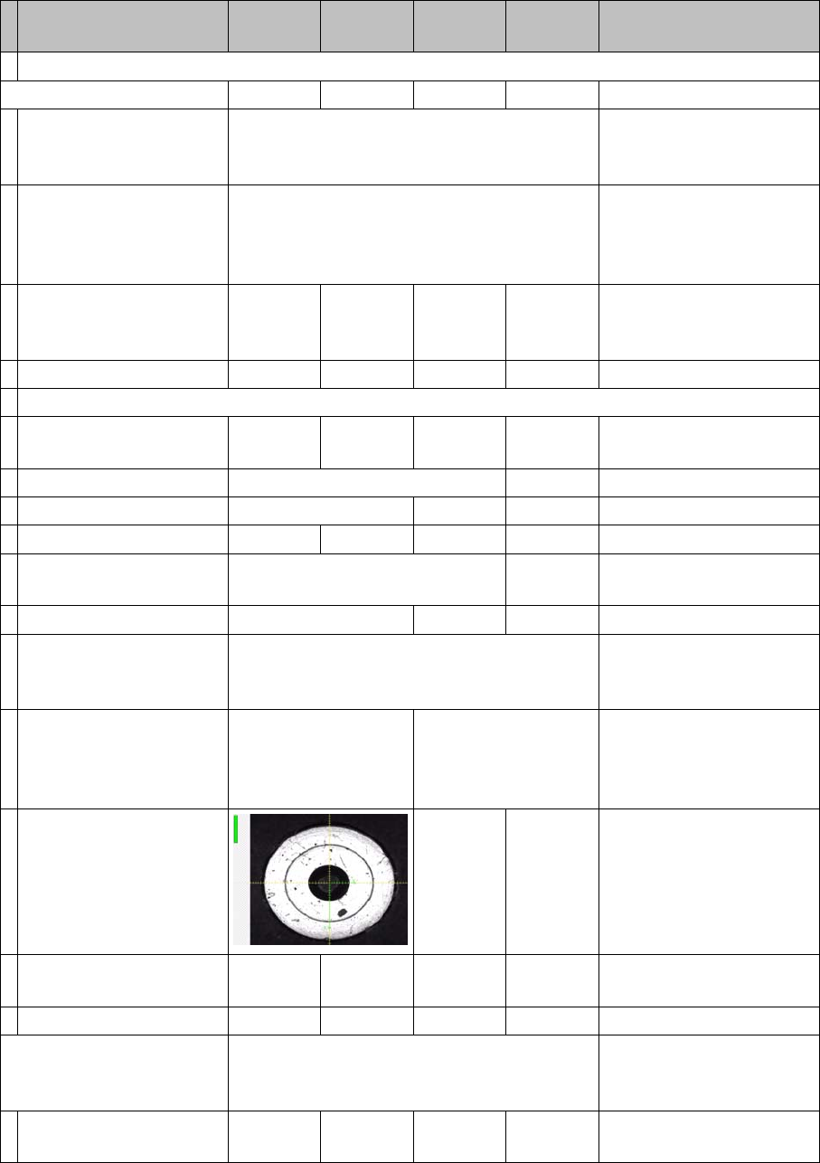
Optically center fiducial
at machine measure-
ment point with PCB
camera.
Measuring point PA1
and PA2
Measuring point PA1 As single step in: 'gantry'
'position calib' 'MA 0 point'
Correct X /Y axis zero
point correction by calcu-
lated offset.
Perform axis reference
run.
Save in Achs_ver.ma.
Calibrating PCB camera YES Automatically in 'all heads/
cameras' with Vision im-
age
Move to calibration tool
and
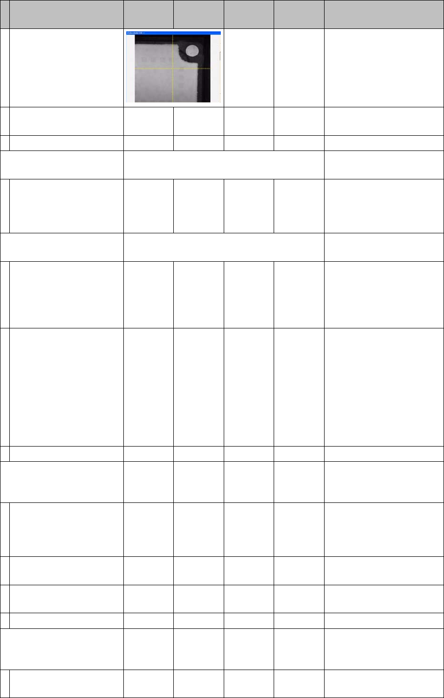
16 Annex (FSE)
16.3 Calibration Steps and Individual Calibration Functions
Student Guide SIPLACE D-Series (FSE) 269
calibrate the 2 mm PCB
camera fiducial at the 4
corners.
As single step in: 'gantry'
'PCB camera calibration'
Repeat measuring pro-
cedure.
Save in camera.xml.
Calibrating calibration tool
position
Selectable in 'all heads/ cameras' with
Vision image
Move to calibration tool
target position and
measure the 2 mm fidu-
cial center.
As single step in: 'gantry'
'position calib'
'calibration tool position'
Calibrating travel range X/
Y gantry axes
Selectable in 'all heads/ cameras'
Move X-axis to bumper
position / move to 0
pulse/ move to 2nd
bumper/ perform refer-
ence run several times.
As single step in: 'gantry'
'axes' 'X or Y axis ' 'travel
range'
Move Y-axis to bumper
position / move to 0
pulse/ move to 2nd
bumper/ perform refer-
ence run several times.
--> <--
PA with
single
gantry
-->
--> <-- Move Y-axis to bumper
outside position /SW exe-
cutes this for both gantries
in sequence / this deter-
mines the min. Y pos.1(2)
max. Y pos. 4 (3) - the oth-
er limit pos. is calculated /
perform reference run sev-
eral times.
Save in Achs_ver.ma.
Calibrating head height
(head 2 P&P module )
YES
With
TWIN
YES Automatically in 'all heads/
cameras'
Move TWIN segment/
P&P module to fixed con-
veyor side.
Calibration nozzle 517
As single step in: 'P&P
module' 'calib head' 'calibr.
head height'
Position Z-axis on top
edge of conveyor side.
Perform Z-axis reference
run.
Save in
Calibrating comp. camera
1 (head 2 P&P module)
YES
With
TWIN
YES Automatically in 'all heads/
cameras' with Vision im-
age
Move PCB camera to
calib. tool and calibrate.
Calibration nozzle 517
Calibration step/individu-
al calibration function
For D4/
D4i
For D3 For D2/
D2i
For D1/
D1i
Comments