00195440-05-SG_D-Series_FSE-EN.pdf - 第271页
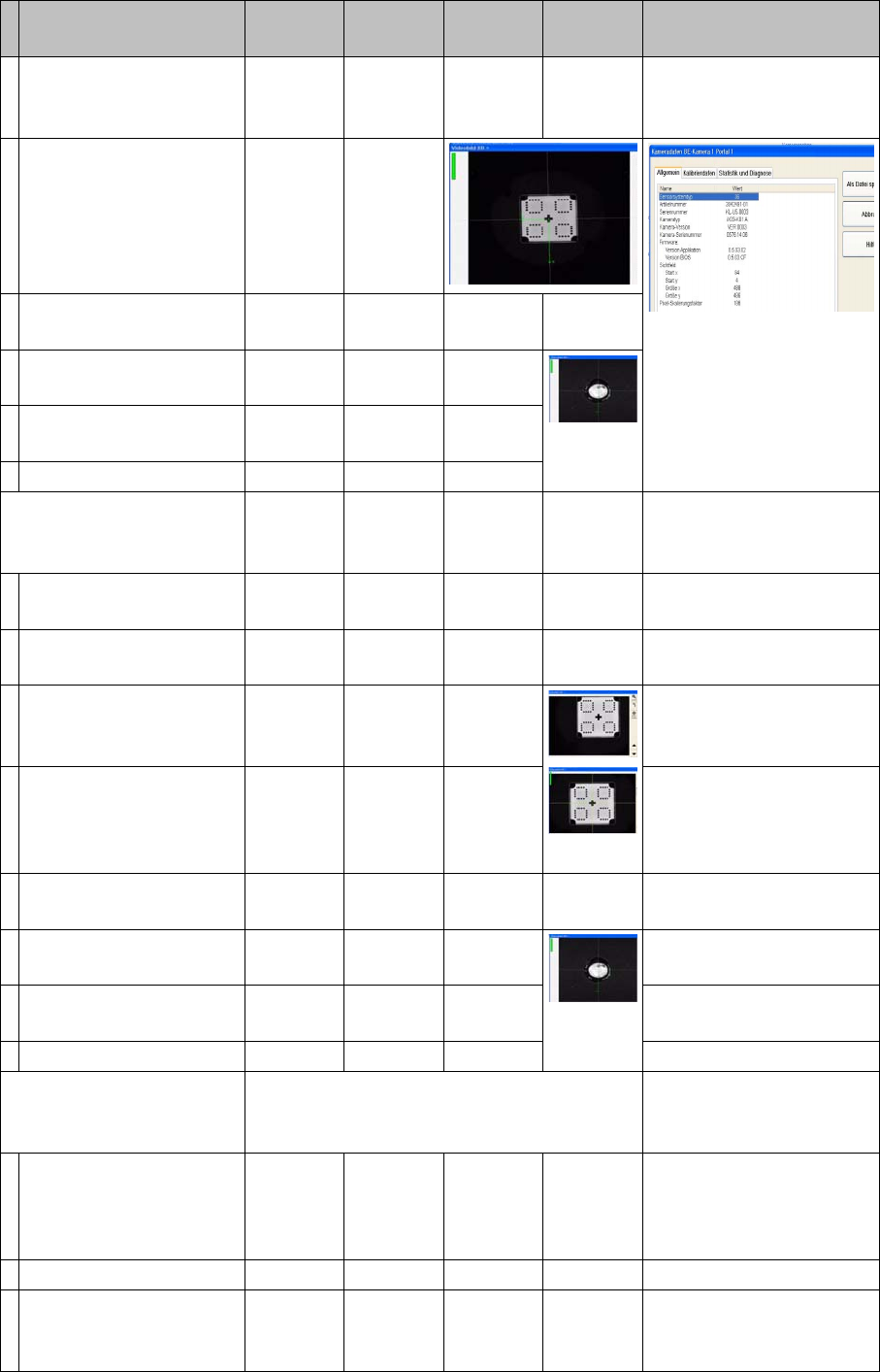
16 Annex (FSE) 16.3 Calibration Steps and Individual Calibration Functions Student Guide SIPLACE D-Series (FSE) 271 Calibrate head. Segment offset I Measure CT with PCB camera. Pick up CT wit h seg. 1 and meas ure 8 time…
16 Annex (FSE)
16.3 Calibration Steps and Individual Calibration Functions
270 Student Guide SIPLACE D-Series (FSE)
Pick up calib. tool and
measure near the 4 cor-
ners.
As single step in: 'P&P
module' 'comp. camera 1
calib.'
Pick up calibration tool
and measure in comp.
camera center in 90°
steps.
Repeat measuring pro-
cedure.
Calibrate camera fidu-
cial.
Repeat measuring pro-
cedure.
Save in camera.xml.
Calibrating comp. camera
2 (head 2 P&P module) op-
tion
YES
With
TWIN
YES Automatically in 'all heads/
cameras' with Vision im-
age
Measure head height on
conveyor and camera.
Move PCB camera to
calib. tool and calibrate.
Calibration nozzle 517
Pick up calib. tool and
measure near the 4 cor-
ners.
As single step in: 'P&P
module' 'comp. camera 2
calib.'
Pick up calibration tool
and measure in comp.
camera center in 90°
steps.
Repeat measuring pro-
cedure.
Calibrate camera fidu-
cial.
Repeat measuring pro-
cedure.
Save in camera.xml.
Calibrate head (head 1 RV
.. head ) (with comp. cam-
era)
YES Automatically in 'all heads/
cameras' with Vision im-
age
Move PCB camera to
calib. tool and calibrate.
As single step in: 'C&P
head/RV head' 'comp.
camera calib'
Check the results there.
Calibrate camera. 956 nozzle
Pick up calib. tool and
calibrate comp. camera.
Return CT.
Save in camera.xml.
Calibration step/individu-
al calibration function
For D4/
D4i
For D3 For D2/
D2i
For D1/
D1i
Comments

16 Annex (FSE)
16.3 Calibration Steps and Individual Calibration Functions
Student Guide SIPLACE D-Series (FSE) 271
Calibrate head.
Segment offset I
Measure CT with PCB
camera.
Pick up CT with seg. 1
and measure 8 times in
90° steps.
Calibrate segment offset I
(top).
Rotary axis of segment to
comp. camera center
Repeat this with all seg-
ments.
Save in Pip_off.ma.
Segment offset II
Measure CT pos. with
PCB cam. / pick up with
seg.1 in 0° pos./ opt. cen-
tering & return.
Segment pickup angle in
the
4 90° steps
Repeat previous step
with seg.1 in 90; 180,
270° pos.
Repeat the two previous
steps with all other seg-
ments.
Save in Pip_off.ma.
For saving, see -->
Calibrating head (head 2
P&P module )
YES
With
TWIN
YES Automatically in 'all heads/
cameras'
Calibrate camera posi-
tion for comp. camera 1
and 2.
As single step in: 'P&P
module' 'head calib.' 'head
calib.' / segment calib.
The positions of the sta-
tionary cameras are
measured in 90° steps.
517 nozzle
Save in camera.xml.
Calibrating nozzle changer
head 1
YES In 'all heads/ cameras', in
part with Vision image
During automatic calib.
the 1st fiducial is not
shown to operator for
confirmation; the pickup/
place sequence runs
through to end .*
With single step, the 1st fi-
ducial is shown to the op-
erator for confirmation.
The pickup/place se-
quence is processed as if
segment 1 is occupied.
Measure X/Y position of
magazine and reject po-
sition with PCB camera.
As single step in: 'C&P
head/RV head' 'Nozzle ch.
magazine function.' 'noz.
ch. calib.' You can select/
deselect the reject pos. /
pickup height.
The pickup height is cal-
culated by picking up/
placing a nozzle in ga-
rage 1 with segment 1.
Calibration step/individu-
al calibration function
For D4/
D4i
For D3 For D2/
D2i
For D1/
D1i
Comments
16 Annex (FSE)
16.3 Calibration Steps and Individual Calibration Functions
272 Student Guide SIPLACE D-Series (FSE)
"Pickup height" measurement is performed fastest with an empty segment
1 and a full garage 1 in all magazines.
Save in PPW_ver.ma.
Calibrating nozzle changer
head 2
YES
With
TWIN
YES In 'all heads/ cameras', in
part with Vision image
During automatic calib.
the 1st fiducial is not
shown to operator for
confirmation; the pickup/
place sequence runs
through to end .*
With single step, the 1st fi-
ducial is shown to the op-
erator for confirmation
Measure X/Y position of
magazines and whole
changer with PCB cam-
era.
As single step in: 'C&P
head/RV head' 'Nozzle ch.
magazine function.' 'noz.
ch. calib.' You can select/
deselect the reject pos. /
pickup height.
The pickup height is cal-
culated by inserting a 5xx
nozzle into an empty ga-
rage.
TWIN module 1 must carry one nozzle and there must be one garage
empty in all the magazines. This is required for measurement in automatic
mode to be performed.
Save in PPW_ver.ma.
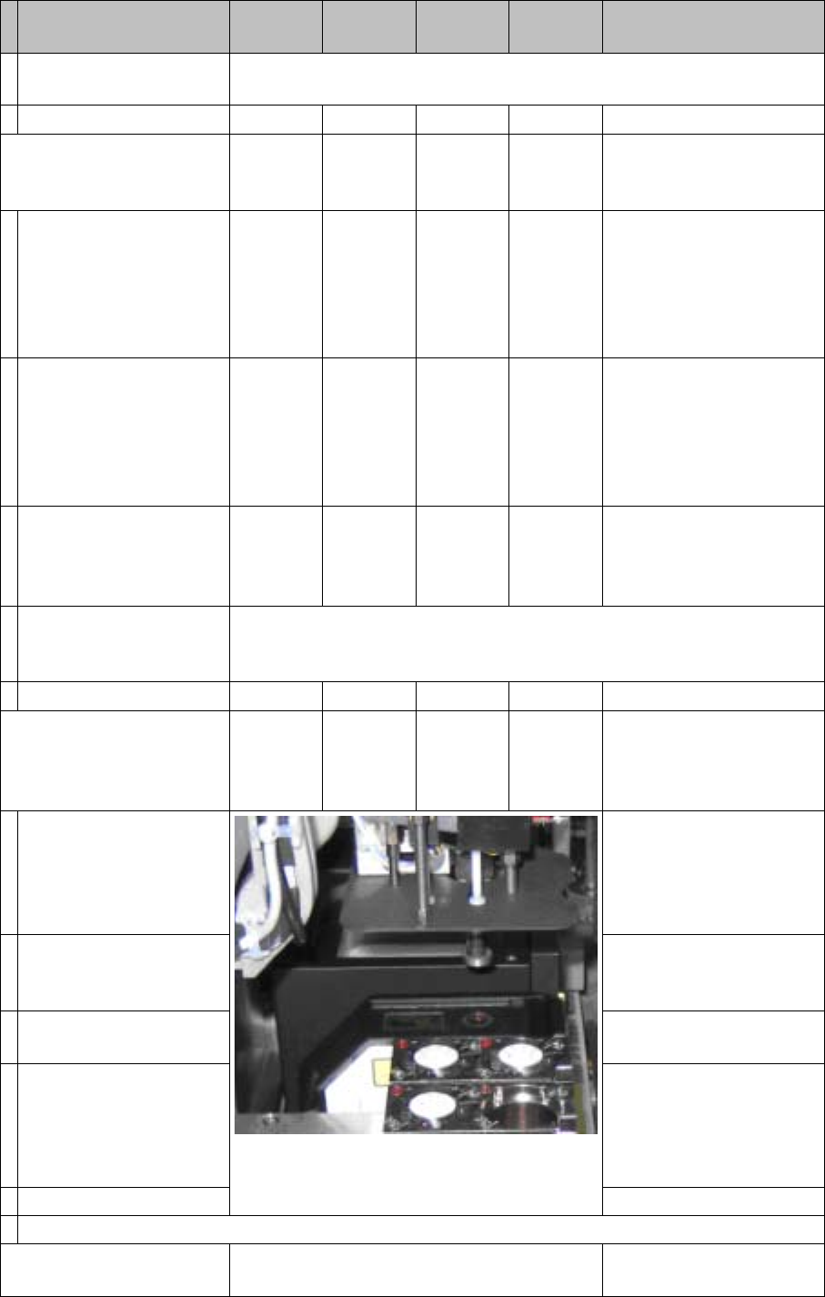
Calibrating coplanarity
(head 2 P&P module) (1 D
coplanarity)
YES
With
TWIN &
ILD
YES
With
ILD2200
Semi-automatically in 'all
heads/ cameras' without
Vision image
After all calibrations with
the Vision CT have been
completed, the proce-
dure stops with 'prepare
PA'.
517 nozzle
The Vision CT must be re-
placed with the coplanarity
CT.
Copl. CT is picked up.
Measure on the top edge
of the conveyor side.
As single step in: 'P&P
module' 'coplanarity' 'cali-
brate coplan.'
The focus height of the
laser is measured.
The X/Y outer edges of
the coplanarity CT are
measured in 90° steps,
to determine the laser
beam position.
Save in coplan.ma.
Semiautomatic calibration menus or menus which are activated in single step mode.
Calibrating the conveyor
sides
YES To be manually calibrated
Calibration step/individu-
al calibration function
For D4/
D4i
For D3 For D2/
D2i
For D1/
D1i
Comments