00195440-05-SG_D-Series_FSE-EN.pdf - 第274页
16 Annex (FSE) 16.3 Calibration Steps and Individual Calibration Functions 274 Student Guide SIPLACE D-Series (FSE) I f t h e W P C i s r e c o g n i z e d by SITEST on the D1/D1i table, chang eover table 1 will be calib…
16 Annex (FSE)
16.3 Calibration Steps and Individual Calibration Functions
Student Guide SIPLACE D-Series (FSE) 273
The position of the flexi-
ble conveyor side when
moving apart is meas-
ured in 30 (12 dual con-
veyor) steps.
As single step in 'convey-
or' 'calibrate conveyor'
The position of the flexi-
ble conveyor side when
moving together is meas-
ured in 30 steps.
Save in conveyor control
'backup in TSP.MA'.
Calibrating the conveyor
widths
YES
As single step in 'convey-
or' 'calibrate conveyor'
Save in conveyor control. Can be manually set e.g.
to 100 mm. This is then
the basis for 'conveyor
width nominal value' with
tolerance.
PCB reference corner YES
Adjust conveyor width
automatically to board
width with SW e.g. 100
mm.
As single step in 'gantry'
'gantry positions'
Place the board (no need
to put it on the LB posi-
tion) into the input con-
veyor.
PCB is automatically
moved in and clamped
into place.
The gantry positions the
PCB camera into the cur-
rently programmed X/Y
position. The operator
teaches the new position
with the PCB camera.
When you exit the teach
menu, the data will be ac-
cepted.
Save in REAL.MA.
Calibrating the Pickup Po-
sition
YES
Place zero point gauge
(iron) on changeover ta-
ble 1, track 1.
As single step in 'convey-
or' 'calibrate conveyor'
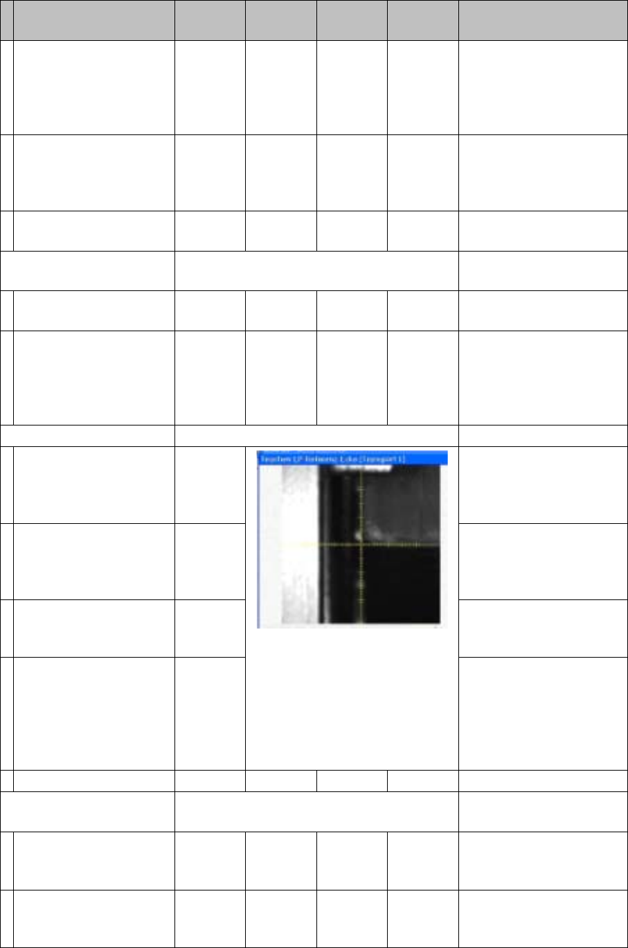
PCB camera centers 1.5
mm drilling for the pickup
coordinates of track 1.
The pickup positions of the
different feeders are be-
tween these coordinates.
Calibration step/individu-
al calibration function
For D4/
D4i
For D3 For D2/
D2i
For D1/
D1i
Comments

16 Annex (FSE)
16.3 Calibration Steps and Individual Calibration Functions
274 Student Guide SIPLACE D-Series (FSE)
If the WPC is recognized
by SITEST on the D1/D1i
table, changeover table 1
will be calibrated with
track 61 and 90. If the
WPC is OFF, calibration
will be performed from
track 1 to 90.
Repeat the function for
track 90 (track 72 for D4/
D4i).
For precision purposes,
only use one 'iron' per lo-
cation, so that the feeder
pickup position in the table
center is not affected.
Repeat this function for
all other changeover ta-
bles.
Save in REAL.MA.
Calibrating the closed vac-
uum
For (head 2 P&P module)
YES
With
TWIN
YES In 'P&P module' 'calibrate
head'
The TWIN module picks
up a 518 nozzle from the
nozzle changer.
518 nozzle
The 518 nozzle is moved
to the top edge of the
conveyor side, to meas-
ure the vacuum.
The rubber membrane of
the 518 nozzle is sealed
onto the edge of the con-
veyor side. The measured
vacuum is the same as the
closed vacuum value for
the C&P heads.
Save in --- …. … the closed vacuum is
measured at each refer-
ence run.
Zero adjustment vacuum
For (head 2 P&P module)
YES
With
TWIN
YES In 'P&P module' 'head
board'
The air blast vacuum is
adjusted to '0'.
The compressed air sup-
ply is disabled.
This is the real '0' state.
The vacuum difference is
measured and after reac-
tivation, the electronic
control valve is set to the
new 0 value.
The nozzle must not be
manually blocked/closed.
Save in control valve
EPROM
Calibrating the zero point
correction D/Di-axis
For (head 2 P&P module)
YES
With
TWIN
YES In 'P&P module' 'calibrate
head'
Calibration step/individu-
al calibration function
For D4/
D4i
For D3 For D2/
D2i
For D1/
D1i
Comments

16 Annex (FSE)
16.3 Calibration Steps and Individual Calibration Functions
Student Guide SIPLACE D-Series (FSE) 275
Replace the current noz-
zle on the TWIN module
with the special calibra-
tion nozzle, according to
the SW message.
The gantry moves the
TWIN module above the
component (IC) camera.
Within a +/-5° tolerance,
the SW determines the
angle correction.
Save in Achs_ver.ma.
Calibration menus reserved for SIPLACE Service
FCCS for digital cameras White adjustment of hard-
ware required.
The PCB camera cali-
brates the calibration tool
carrier position after this
carrier has been moved
into the PCB conveyor
and clamped into place.
Other PCB camera test
measurements follow.
All cameras programmed
in the Config.ma file are
brightness calibrated via
a whiteness adjustment
measurement.
Save in camera EPROM! The results can be saved
in the calibration value
XML file.
Checking the star mounting
position in the magnetic
neutral position
The star mounting posi-
tion is checked by com-
paring the magnetic
neutral position with the
'zero position of segment
1'.
A deviation of up to 95x 1/
1000° is tolerated by the
SW.
Should errors occur, re-
mount the placement
star on the star motor
shaft.
Calibration step/individu-
al calibration function
For D4/
D4i
For D3 For D2/
D2i
For D1/
D1i
Comments