00195440-05-SG_D-Series_FSE-EN.pdf - 第282页
16 Annex (FSE) 16.6 SIPLACE Vision - Sensor Ove rview 1 6.6.2 Optional Digital Co mponent Camera C&P1 2 (Type 38) 282 Student Guide SIPLACE D-Series (FSE) 16.6.2 1 6 . 6 . 2 O p t io n a l D ig it a l C o m p o n e n…

16 Annex (FSE)
16.6.1 Digital PCB Camera (Type 34) 16.6 SIPLACE Vision - Sensor Overview
Student Guide SIPLACE D-Series (FSE) 281
16.6.1.3
16.6.1.3 Inkspot Criteria
Inkspot Criteria
Fiducial surface
Copper Without oxidation and soldering paste
Tin Warpage 1/10 of the structure width, with good contrast to surround-
ings
Dimensions of synthetic fiducials
Min. X/ Y size for circle and rectangle: 0.25 mm
Min. X/ Y size for square ring and rectangle frame: 0.3 mm
Min. X/ Y size for cross: 0.3 mm
Min. X/ Y size for doublecross: 0.5 mm
Min. X/ Y size for diamond: 0,35 mm
Min. frame width for square ring and rectangle frame: 0,1 mm
Min. bar width/bar spacing for cross, doublecross: 0,1 mm
Max. X/ Y size for all fiducial shapes: 3 mm
Max. bar width/bar spacing for cross, doublecross: 1,5 mm
Min. general tolerances: 2% of nominal dimensions
Max. general tolerances: 20% of nominal dimensions
Max. Winkeltoleranz: 2° für synthetische Marken
5° für Mustermarken
Dimensions of templates
Min. size 0.5 mm
Max. size 3 mm
Fiducial surroundings Space is not needed around the fiducials, provided there are no other
similar fiducial structures in the search field.
Methods ▪ Synthetic fiducial detection procedures
▪ Middle gray value
▪ Histogram method
▪ Template matching
Size of fiducial shapes or structures
Synthetic Fiducials For dimensions of synthetic fiducials, see "16.6.1.2 Fiducial Criteria"
[ ➙ 280].
Other methods Min. 0,3 mm
max. 3 mm
Cover material Covers well
Recognition time Depending on method, 20 ms - 0.2 s
16 Annex (FSE)
16.6 SIPLACE Vision - Sensor Overview 16.6.2 Optional Digital Component Camera C&P12 (Type 38)
282 Student Guide SIPLACE D-Series (FSE)
16.6.2
16.6.2 Optional Digital Component Camera C&P12 (Type 38)
Optional Digital Component Camera C&P12 (Type 38)
16.6.2.1
16.6.2.1 Technical data
Technical data
Technical data for camera type 38
16.6.3
16.6.3 Digital Component Camera C&P12 (Type 28)
Digital Component Camera C&P12 (Type 28)
16.6.3.1
16.6.3.1 Technical data
Technical data
Technical data for camera type 28
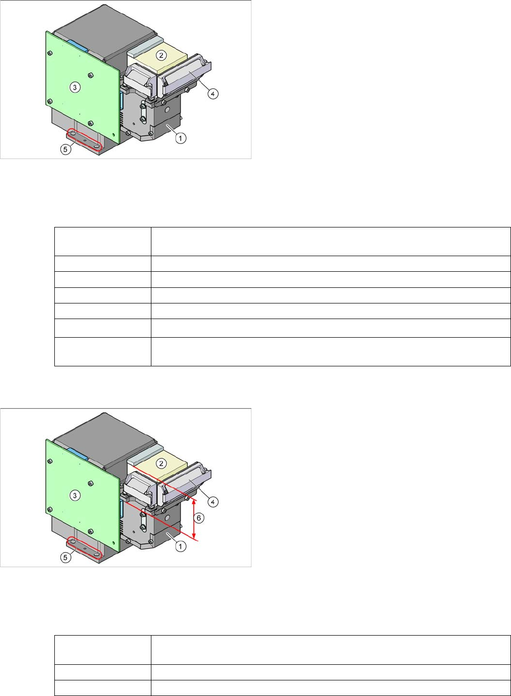
Component camera as option on the C&P12 head
Legend
1. Component camera optics and illumination
2. Camera amplifier
3. Illumination control
4. Flat ribbon cable holder for C&P head leads
5. Camera fixtures
2 x fixture drillings and 1 x centering drilling each on
both sides
The camera type 38 can be recognized by its type label.
Component dimen-
sions
0.2 x 0.1 mm
2
to 16 x 16 mm
2
Component range 0.2 x 0.1 mm² (01005) to PLCC36 (32R)
Min. lead pitch 0,1 mm
Min. ball pitch 0.25 mm
Min. ball diameter 0.14 mm
Field of vision
20.5 x 20.5 mm
2
Method of illumina-
tion
Front lighting (6 programmable options on 4 levels )
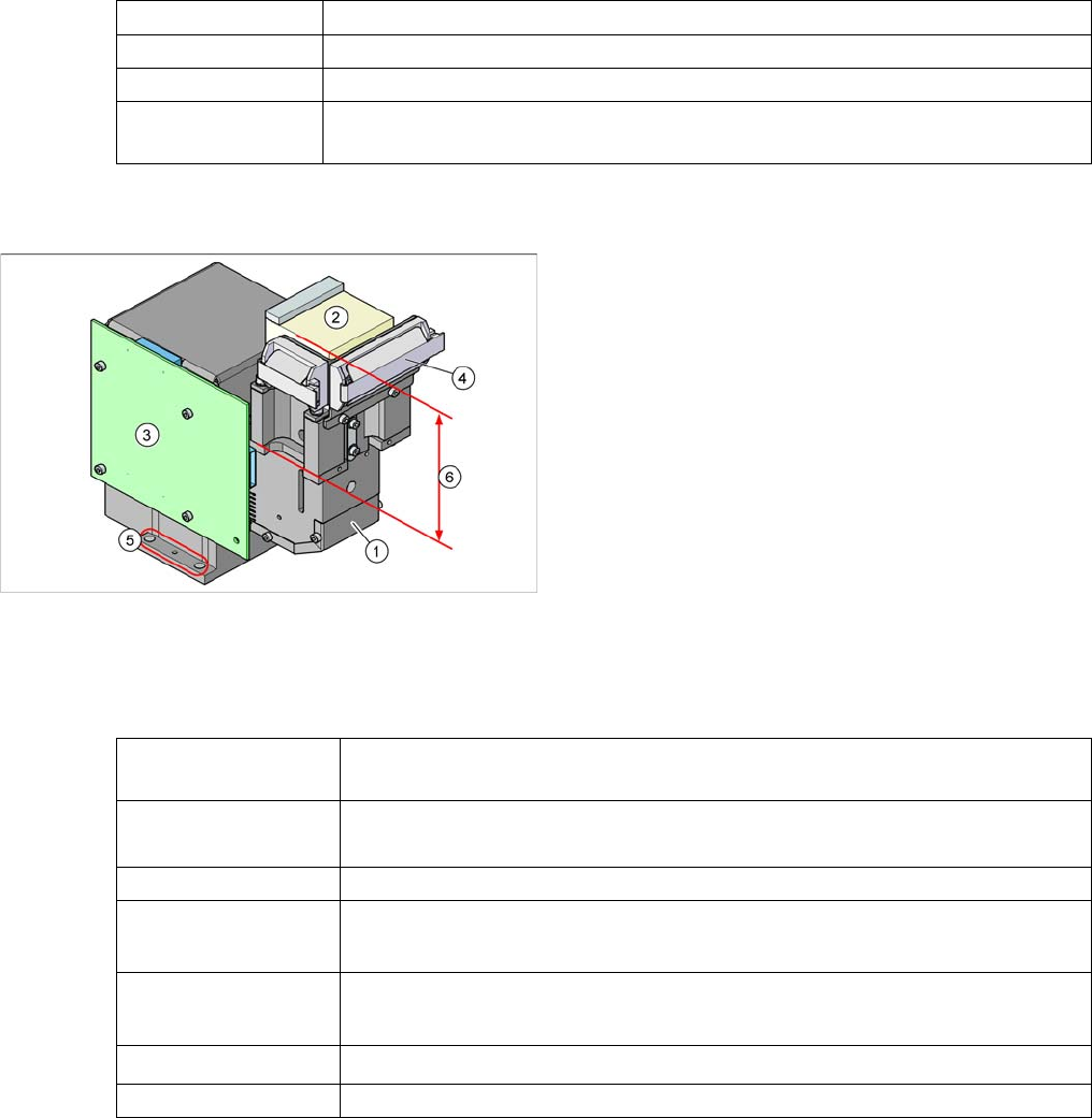
Component camera as default on the C&P12 head
Legend
1. Component camera optics and illumination
2. Camera amplifier
3. Illumination control
4. Flat ribbon cable holder for C&P head leads
5. Camera fixtures
2 x fixture drillings and 1 x centering drilling each on
both sides
6. The low construction helps you to differentiate cam-
era type 28 from camera type 29.
Component dimen-
sions
0.5 x 0.5 mm
2
to 18.7 x 18.7 mm
2
Component range 0402 to PLCC44 incl. BGA, µBGA, flip-chip, TSOP, QFP, SO to SO32, DRAM
Min. lead pitch 0.5 mm
16 Annex (FSE)
16.6.4 Component Camera C&P12 (Optional, Type 29) 16.6 SIPLACE Vision - Sensor Overview
Student Guide SIPLACE D-Series (FSE) 283
16.6.4
16.6.4 Component Camera C&P12 (Optional, Type 29)
Component Camera C&P12 (Optional, Type 29)
16.6.4.1
16.6.4.1 Technical data
Technical data
Technical data for camera type 29
Min. ball pitch 0.45 mm
Min. ball diameter 0.25 mm
Field of vision 24.5 x 24.5 mm2
Method of illumina-
tion
Front lighting (6 programmable options on 4 levels )
Component camera as default on the C&P12 head
Legend
1. Component camera optics and illumination
2. Camera amplifier
3. Illumination control
4. Flat ribbon cable holder for C&P head leads
5. Camera fixtures
2 x fixture drillings and 1 x centering drilling each on
both sides
6. The high construction helps you to differentiate cam-
era type 29 from camera type 28.
Component dimen-
sions
0.3 x 0.3 mm
2
to 27 x 27 mm
2
Component range
0201 to 27 x 27 mm
2
PLCC, SO, QFP, TSDP, SOT, MELF, CHIP, IC, BGA
Min. lead pitch 0.3 mm
Min. ball pitch
0.25 mm for component < 18 x 18 mm
2
0.35 mm for component ≥ 18 x 18 mm
2
Min. ball diameter
0.14 mm for component < 18 x 18 mm
2
0.2 mm for component ≥ 18 x 18 mm
2
Field of vision
31 x 31 mm
2
Method of illumination Front lighting (6 programmable options on 4 levels )