00195440-05-SG_D-Series_FSE-EN.pdf - 第284页
16 Annex (FSE) 16.6 SIPLACE Vision - Sensor Overview 16.6.5 Component Camera C& P12 (Optional, Type 30) 284 Student Guide SIPLACE D-Series (FSE) 16.6.5 1 6 . 6 . 5 C o m p o n e n t C a m e r a C & P 1 2 ( O p t …
16 Annex (FSE)
16.6.4 Component Camera C&P12 (Optional, Type 29) 16.6 SIPLACE Vision - Sensor Overview
Student Guide SIPLACE D-Series (FSE) 283
16.6.4
16.6.4 Component Camera C&P12 (Optional, Type 29)
Component Camera C&P12 (Optional, Type 29)
16.6.4.1
16.6.4.1 Technical data
Technical data
Technical data for camera type 29
Min. ball pitch 0.45 mm
Min. ball diameter 0.25 mm
Field of vision 24.5 x 24.5 mm2
Method of illumina-
tion
Front lighting (6 programmable options on 4 levels )
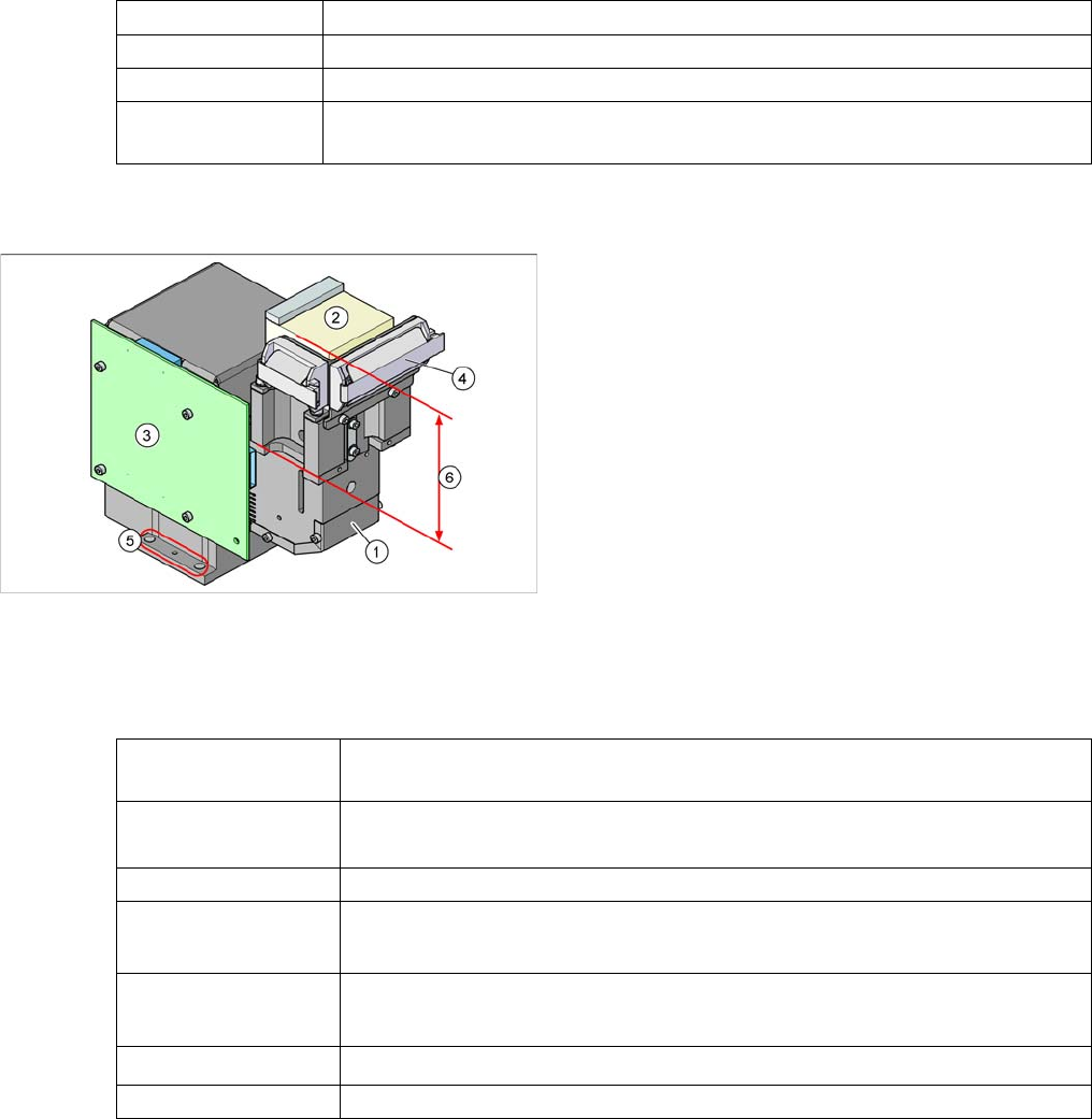
Component camera as default on the C&P12 head
Legend
1. Component camera optics and illumination
2. Camera amplifier
3. Illumination control
4. Flat ribbon cable holder for C&P head leads
5. Camera fixtures
2 x fixture drillings and 1 x centering drilling each on
both sides
6. The high construction helps you to differentiate cam-
era type 29 from camera type 28.
Component dimen-
sions
0.3 x 0.3 mm
2
to 27 x 27 mm
2
Component range
0201 to 27 x 27 mm
2
PLCC, SO, QFP, TSDP, SOT, MELF, CHIP, IC, BGA
Min. lead pitch 0.3 mm
Min. ball pitch
0.25 mm for component < 18 x 18 mm
2
0.35 mm for component ≥ 18 x 18 mm
2
Min. ball diameter
0.14 mm for component < 18 x 18 mm
2
0.2 mm for component ≥ 18 x 18 mm
2
Field of vision
31 x 31 mm
2
Method of illumination Front lighting (6 programmable options on 4 levels )
16 Annex (FSE)
16.6 SIPLACE Vision - Sensor Overview 16.6.5 Component Camera C&P12 (Optional, Type 30)
284 Student Guide SIPLACE D-Series (FSE)
16.6.5
16.6.5 Component Camera C&P12 (Optional, Type 30)
Component Camera C&P12 (Optional, Type 30)
16.6.5.1
16.6.5.1 Technical data
Technical data
Technical data for camera type 30
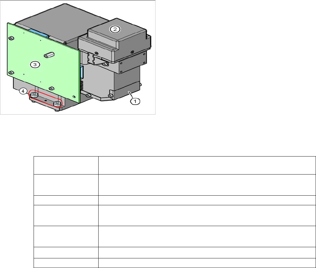
Component camera as default on the C&P12 head
Legend
1. Component camera optics and illumination
2. Camera amplifier
3. Illumination control
4. Camera fixtures
2 x fixture drillings and 1 x centering drilling each on
both sides
Component dimen-
sions
0.18 x 0.18 mm
2
to 27 x 27 mm
2
Component range
01005 to 27 x 27 mm
2
CHIP, PLCC, SO, QFP, TSDP, SOT, MELF, IC, BGA
Min. lead pitch 0.25 mm
Min. ball pitch
0.25 mm for component < 18 x 18 mm
2
0.35 mm for component ≥ 18 x 18 mm
2
Min. ball diameter
0.14 mm for component < 18 x 18 mm
2
0.2 mm for component ≥ 18 x 18 mm
2
Field of vision
32.7 x 32.7 mm
2
Method of illumination Front lighting (5 programmable options on 5 levels )
16 Annex (FSE)
16.6.6 Component Camera (Standard Type 36, Option Type 33) 16.6 SIPLACE Vision - Sensor Overview
Student Guide SIPLACE D-Series (FSE) 285
16.6.6
16.6.6 Component Camera (Standard Type 36, Option Type 33)
Component Camera (Standard Type 36, Option Type 33)
16.6.6.1
16.6.6.1 Technical data
Technical data
Technical data for camera type 36
Technical data for camera type 33
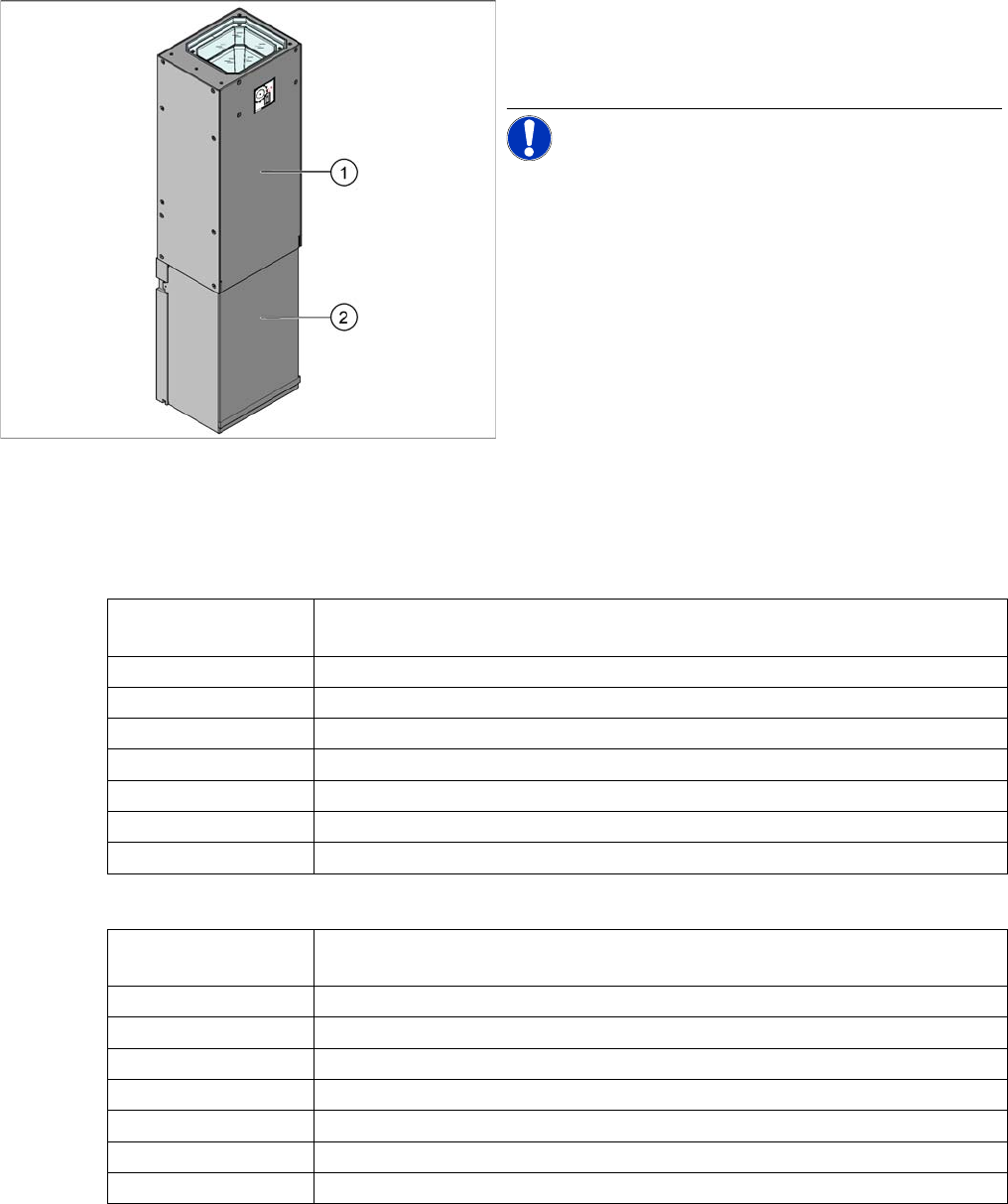
Component camera for Twin head (D3) or P&P module
(D1/D1i)
Legend
1. Top section with camera lens system
2. Lower camera cover
NOTICE! The standard camera (type 36) and
the optional camera (type 33) can be recognized by their
labels.
Component dimen-
sions
0.8 x 0.8 mm² to 32 x 32 mm² (simple measurement)
Component range 0603, MELF, SO, PLCC, QFP, electrolytic capacitors, BGA
Min. lead pitch 0.4 mm
Min. lead width 0.24 mm
Min. ball pitch 0.56 mm
Min. ball diameter 0.32 mm
Field of vision 38 x 38 mm²
Method of illumination Front lighting (6 programmable options on 4 levels )
Component dimen-
sions
0.8 x 0.8 mm² to 55 x 45 mm² (simple measurement)
Component range 0603, MELF, SO, PLCC, QFP, electrolytic capacitors, BGA
Min. lead pitch 0.3 mm
Min. lead width 0.15 mm
Min. ball pitch 0.45 mm
Min. ball diameter 0.25 mm
Field of vision 65 x 50 mm² simple measurement
Method of illumination Front lighting (6 programmable options on 4 levels )