00195440-05-SG_D-Series_FSE-EN.pdf - 第30页
3 Overview 3.4 Assemblies 3.4.2 Sectors 30 Student Guide SIPLACE D-Series (FSE) 3.4.2 3 . 4 . 2 S e c t o r s Sectors Sector 1: ▪ Transport control TSP 301 ▪ CAN interface CAN Bus baudr ate 500 KBit/s for S tables ▪ Asse…
3 Overview
3.4.1 General Overview of Assemblies 3.4 Assemblies
Student Guide SIPLACE D-Series (FSE) 29
3.4.1
3.4.1 General Overview of Assemblies
General Overview of Assemblies
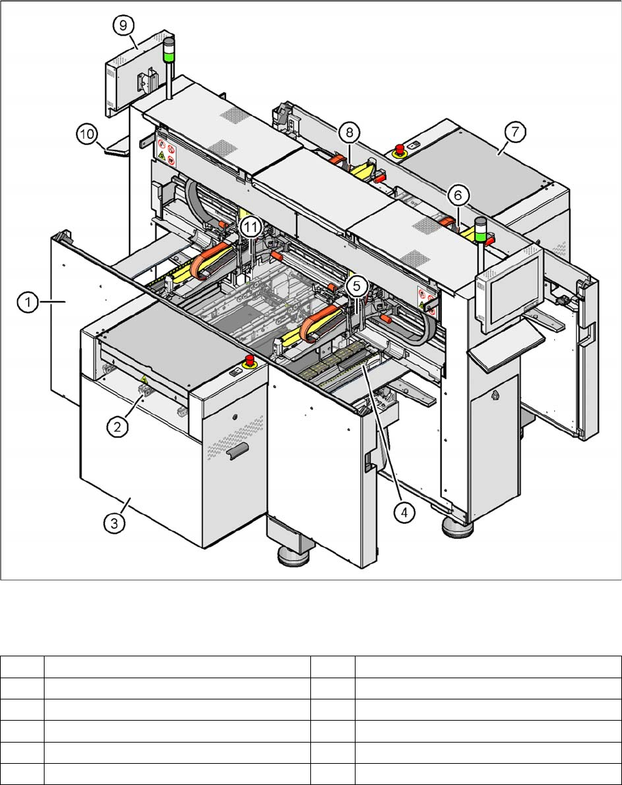
Overview of the modules
Legend
1 Machine frame 7 Extension kit on the PCB output side
2 PCB conveyor (flexible dual conveyor) 8 Gantry 3
3 Extension kit on the PCB input side 9 Monitor (2x)
4 Tape cutter , empty tape duct (4x) 10 Keyboard (2x)
5 Gantry 1 11 Gantry 4
6 Gantry 2
3 Overview
3.4 Assemblies 3.4.2 Sectors
30 Student Guide SIPLACE D-Series (FSE)
3.4.2
3.4.2 Sectors
Sectors
Sector 1:
▪ Transport control TSP 301
▪ CAN interface CAN Bus baudrate 500 KBit/s for S tables
▪ Assembly A3 CAN terminating resistor for S table location 1
▪ Vision DC/DC converter illumination digital camera gantry 1 - 4 (03002280-02)
▪ Terminal X100 power supply
▪ Pneumatic switch for changeover table 1
Sector 2:
▪ CAN I/O module 2 with CAN interface 500 KBit/s for S tables
▪ Assembly A3 CAN terminating resistor for S table location 2
▪ 3x fuse 24 V
▪ Relay K1 station – compressed air shutoff
▪ Terminal X200 power supply
▪ Pneumatic switch for changeover table 2
Sector 3:
▪ CAN interface CAN Bus baudrate 500 KBit/s for S tables
▪ Assembly A3 CAN terminating resistor for S table location 3
▪ Terminal X300 power supply
▪ Pneumatic switch for changeover table 1
Sector 4:
▪ CAN I/O module 2 with CAN interface 500 KBit/s for S tables
▪ Assembly A3 CAN terminating resistor for S table location 4
▪ 3x fuse 24 V
▪ Terminal X400 power supply
▪ Pneumatic switch for changeover table 1
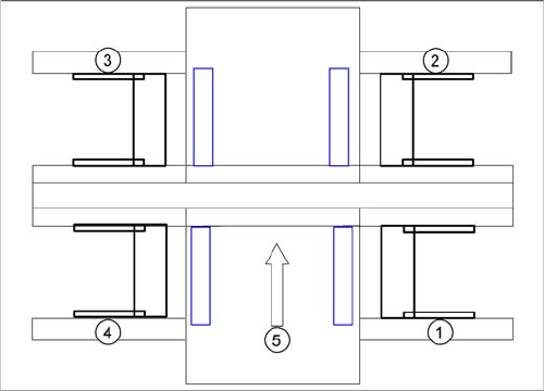
SIPLACE D4 sectors
Legend
1. Sector 1
2. Sector 2
3. Sector 3
4. Sector 4
5. Transport direction
3 Overview
3.4.3 Axis Unit and Computer Unit 3.4 Assemblies
Student Guide SIPLACE D-Series (FSE) 31
3.4.3
3.4.3 Axis Unit and Computer Unit
Axis Unit and Computer Unit
Axis unit 1 – installation set on the PCB input side:
▪ Servo board X, Y, star, Z, DP for PA1
▪ 3x Axis board A364
▪ 2x power supply 5 V/15 A, +/-15 V
Computer unit
▪ Box PC with CD-ROM drive (SR, SIPLACE Vision) or Single BoxPC (SR, SIPLACE Vision, MC)
▪ Micro Box PC (MC) or No Micro Box PC (MC) if system runs with Single BoxPC
▪ Multiplexer or Video Splitter if system runs with Single BoxPC
▪ USB hub
Axis unit 2 – installation set on the PCB output side:
▪ Servo board X, Y, star, Z, DP for PA2
▪ 3x Axis board A364
▪ 2x power supply 5 V/15 A, +/-15 V
▪ Ballast circuit
3.4.3.1
3.4.3.1 Computer Unit
Computer Unit
Axis unit and computer unit
Legend
1. Sector 1
2. Sector 2
3. Sector 3
4. Sector 4
5. Transport direction
6. Axis unit 1
7. Computer Unit
8. Axis unit 2
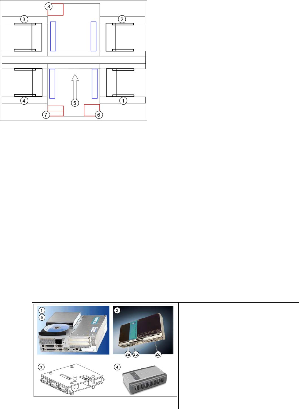
Computer unit D4
Legend
1. Station Computer SIPLACE BoxPC
2. Machine Controller SIPLACE Micro Box-
PC
3. Multiplexer
4. USB hub
5. USB CD-ROM drive