00195440-05-SG_D-Series_FSE-EN.pdf - 第33页
3 Overview 3.4.3 Axis Unit and Computer Unit 3.4 Assemblies Student Guide SIPLACE D-Series (FSE) 33 2. Video Spliter ▪ 1x VGA INPUT Connection to 2x VGA OU PUT Connection (for Displa y Monitors) ▪ 1x USB Male Connection …
3 Overview
3.4 Assemblies 3.4.3 Axis Unit and Computer Unit
32 Student Guide SIPLACE D-Series (FSE)
1. Station Computer SIPLACE BoxPC (SR-SW, SIPLACE Vision-SW)
▪ 2x Hotlink boards for SIPLACE Vision, connected to the digital cameras
▪4x USB port
▪ 2x LAN Ethernet (LAN 1 connected to MC, LAN 2 hub or SIPLACE Pro)
▪ 1x VGA connection, connected to Multiplexer (monitor)
▪ Voltage supply 24 V DC
▪ The status display and the H1/H2 are active on the computer counterpart, while the BIOS is loaded.
2. Machine Controller SIPLACE Micro BoxPC (RMOS-SW)
▪ 2x LAN Ethernet (LAN 1 (2c) connected to SC, LAN 2 - not in use)
▪4x USB port
▪ 1x VGA connection, connected to Multiplexer (monitor)
▪ COM assembly – CAN 1 (2a) for PA1– CAN 2 (2b) for PA2
▪ Voltage supply 24 V DC
3. Multiplexer (switch over between SR and MC)
4. USB-Hub 2.0 – 4-Port (bzw. 7-Port) (anzuschliessen am USB-Port 0)
▪ Voltage supply connection
▪ USB input from station computer
▪ 4x (7x) USB outputs - 2x keyboard, 2x touchscreen (3x free)
5. External CD-ROM drive with USB interface (also for MC)
3.4.3.2
3.4.3.2 Computer Unit Di (Single BoxPC)
Computer Unit Di (Single BoxPC)
1. Station Computer SIPLACE Single BoxPC (SR-SW, MC-SW, SIPLACE Vision-SW)
▪ 1x Hotlink board (A24) for SIPLACE Vision, connected to the digital cameras
▪ 1x CAN BUS board – CAN 1 for PA1– CAN 2for PA2
▪4x USB port
▪ 2x LAN Ethernet (LAN 1 - not in use, LAN 2 hub for SIPLACE Pro)
▪ 1x DVI connection, connected to Video Splitter via DVI to VGA Cables (monitor)
▪ Voltage supply 24 V DC
▪ The status display and the H1/H2 are active on the computer counterpart, while the BIOS is loaded.
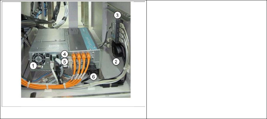
Computer unit Di
Legend
1. Station Computer SIPLACE Single Box-
PC
2. Video Splitter
3. USB hub
4. Hotlink Card (A24)
5. CAN BUS Card
6. DVI to VGA Cable
3 Overview
3.4.3 Axis Unit and Computer Unit 3.4 Assemblies
Student Guide SIPLACE D-Series (FSE) 33
2. Video Spliter
▪ 1x VGA INPUT Connection to 2x VGA OUPUT Connection (for Display Monitors)
▪ 1x USB Male Connection with built-in USB Female Connection (for voltage supply connection)
3. USB-Hub 2.0 – 4-Port (bzw. 7-Port) (anzuschliessen am USB-Port 0)
▪ Voltage supply connection
▪ USB input from station computer
▪ 4x (7x) USB outputs - 2x keyboard, 2x touchscreen (3x free)
4. Hotlink board (A24) for SIPLACE Vision
▪ 4x RJ45 Ports (for SIPLACE Vision, connected to the digital cameras)
5. CAN BUS board
▪ COM assembly – CAN 1 (X11pa) for PA1 – CAN 2 (X12pa) for PA2
6. DVI to VGA Cables
▪ Cable for converting DVI Interface to VGA Interface
3.4.3.3
3.4.3.3 Control Unit Comparison D1/D1i to D4/D4i
Control Unit Comparison D1/D1i to D4/D4i
The control units can be accessed from the left machine side, under the PCB input conveyor belt:
Designation D4/D4i D3 D2/D2i D1/D1i
Station computer Box PC 627/(Sin-
gle BoxPC must be
627B or higher)
PC C086 unit
(from 2007 box PC)
Box PC 627/(Single BoxPC must be
627B or higher)
Operating system Windows XP/(Windows XPe for Single BoxPC)
SC/MC 602.01 / 603.01/(605.03 SP2 for Single
BoxPC for D4i only)
603.01/(605.03 SP2 for Single BoxPC)
Machine controller SIMATIC Micro-
boxPC 420/No Mi-
croboxPC for
Single BoxPC
PC C086 unit
(from 2007 box PC)
SIMATIC Micro-
boxPC 420/No Mi-
croboxPC for
Single BoxPC
SIMATIC Micro-
boxPC 420/No Mi-
croboxPC for
Single BoxPC
Operating system 602: RMOS / 603: Windows XP/(Win-
dows XPe for Single BoxPC for D4i only)
Windows XP/(Windows XPe for Single
BoxPC)
Shutdown - opera-
tor
Regular shutdown of SC / SITEST desk
Shutdown admin-
istrator
Shutdown pushup - start button menu Programs / SIPLACE / Shutdown ALL
External DVD drive Yes for MC with
Windows installa-
tion
Yes for MC with Windows installation
USB connections 4 in SC / 7-fold
USB hub for touch-
screen and key-
board
4 in box PC / 4-fold
USB hub for touch-
screen and key-
board
4 in SC / 7(4)-fold USB hub for touch-
screen and keyboard
CAUTION
Do not switch off!
NEVER switch off during the startup (boot) phase. WINDOWS XP might be unable to restart at
the MC. In this case, you would need to reinstall WINDOWS XP!
3 Overview
3.4 Assemblies 3.4.3 Axis Unit and Computer Unit
34 Student Guide SIPLACE D-Series (FSE)
3.4.3.4
3.4.3.4 Axis Unit
Axis Unit
The axis unit contains the servo boards, axis controller boards, power supply (+/-15V,+5V) and the bal-
last circuit (only in axis unit 2). The flexible axis unit is equipped with the correct servo and axis boards
for the machine type and head configuration concerned (with C&P12).
Overview of axis unit
D4/D4i machine: axis unit in PA1 for gantry 1 and 4, axis units and in PA2 for gantries 2 and 3
Axis Unit SIPLACE D4/D4i
Servo Positions D4/D4i/D2/D2i
Servo assignment D4/D4i/D2/D2i
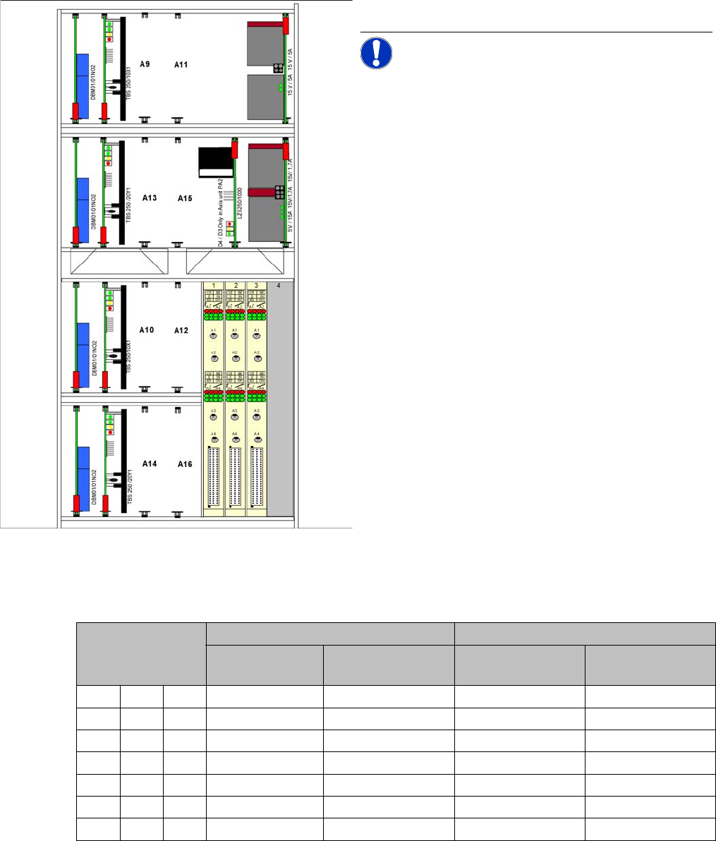
Axis Unit
The axis unit is located near the PCB input or output.
NOTICE! The two power pack assemblies have
a different version from 01/2007 and replace the assem-
blies shown.
Servo positions for
each level
D4/D4i D2/D2i
C&P type
PA1
C&P type
PA2
C&P type P&P type (next
generation)
x Gantry 1 Gantry 2 Gantry 1 Gantry 1
A9 Star 1 Star 2 Star 1 Z-axis 1
A11 Z-axis 1 Z-axis 2 Z-axis 1 --
Y Gantry 1 Gantry 2 Gantry 1 Gantry 1
A13 -- -- -- D axis 1
A15 -- -- -- --
x Gantry 4 Gantry 3 Gantry 2 Gantry 2