00195440-05-SG_D-Series_FSE-EN.pdf - 第37页
3 Overview 3.4.5 Gantry 3.4 Assemblies Student Guide SIPLACE D-Series (FSE) 37 3.4.5 3 . 4 . 5 G a n t r y Gantry 3.4.5.1 3 . 4 . 5 . 1 G e n e r a l General Precise distance measuring syste ms determine the position of …
3 Overview
3.4 Assemblies 3.4.4 Pneumatic Unit
36 Student Guide SIPLACE D-Series (FSE)
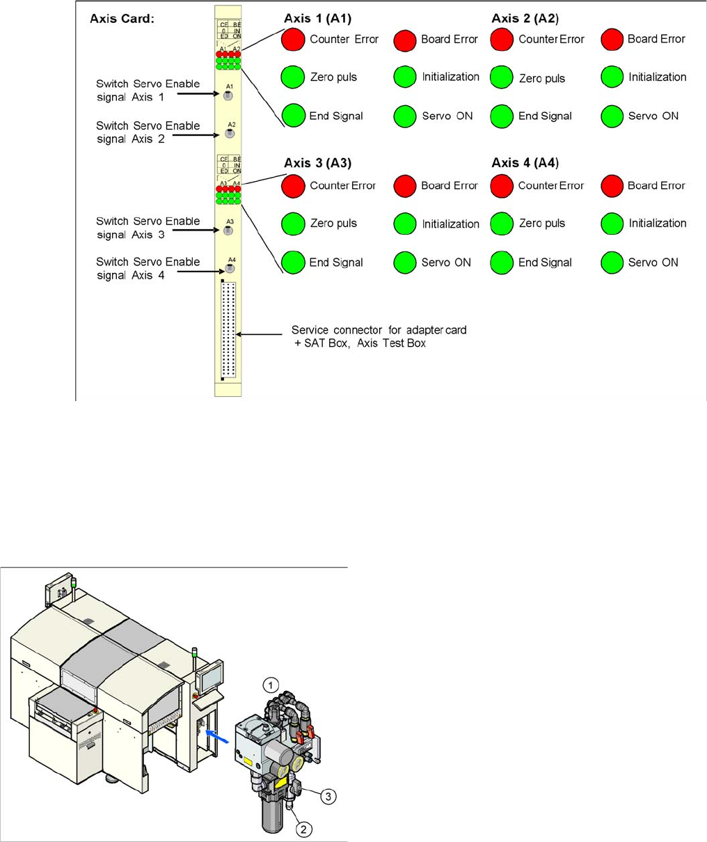
Axis Board A364
D4/D4i axis board
3.4.4
3.4.4 Pneumatic Unit
Pneumatic Unit
The pneumatic unit is a fixed installation inside the machine and is located to the right of the middle sec-
tion of the machine, behind a flap. The pneumatic unit includes all electrical connections for control/reg-
ulation of the compressed air supply.
3.4.4.1
3.4.4.1 D1/D1i/D2/D2i Pneumatic Unit
D1/D1i/D2/D2i Pneumatic Unit
D1/D1i/D2/D2i pneumatic unit
Legend
1. Pneumatic Unit
2. Coupling for compressed air connection
3. Main stop valve
The D1D1i//D2/D2i pneumatic unit is mounted on a com-
pact rack module and is located in the right-hand, middle
section of the machine. The unit is secured by a lockable
door and contains the complete compressed air supply.
In D3 machines, this unit also contains the SMEMA inter-
face (Siemens) to the upstream and downstream sta-
tions.
3 Overview
3.4.5 Gantry 3.4 Assemblies
Student Guide SIPLACE D-Series (FSE) 37
3.4.5
3.4.5 Gantry
Gantry
3.4.5.1
3.4.5.1 General
General
Precise distance measuring systems determine the position of the X and Y axes. This involves the op-
toelectronic detection of marker lines on the incremental scales and the transmission of the track signals
to the axis control point in the control unit.
Direct drive techniques are then used to position the placement heads in the Y direction (in the X direc-
tion also for D3 machines). This prevents the typical frictional loss which occurs when complex drive sys-
tems are used. This solution also avoids the wear and tear which can significantly impair the accuracy
of positioning systems over time.
X-axis drive
With the help of a toothed belt, the rotary movement of the X-axis motor is directly converted into a
lengthwise movement of the placement head, in the X-direction.
Y-axis drive
A linear motor moves the placement head lengthwise, in the Y direction.
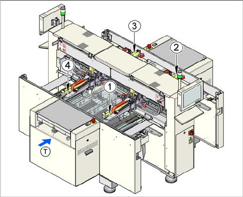
Machine gantries
Legend
1. Gantry 1
2. Gantry 2
3. Gantry 3
4. Gantry 4
The D4/D4i placement machine is equipped with four
gantries. These are used to accurately and independent-
ly position the four C&P heads in the X and Y directions.
Due to their construction, the gantries are resistant to
buckling. The precise mechanical guidance of the axes is
achieved with the aid of ball bearing units.
3 Overview
3.4 Assemblies 3.4.6 Changeover Table Components
38 Student Guide SIPLACE D-Series (FSE)
3.4.6
3.4.6 Changeover Table Components
Changeover Table Components
3.4.6.1
3.4.6.1 Overview of S-Feeder
Overview of S-Feeder
Description: 9 different feeders are enough to process tapes with widths from 8 to 88 mm. The tape reels
on the feeder are taken up by the component trolley tape container. The cutter then cuts up the empty
tape automatically. SIPLACE feeders are known for their short cycle times and highly accurate pickup
positions.
These feeders can also be used in other SIPLACE placement machines.
In addition to the tape feeders, bulkcase feeders, linear feeders, surftape feeders, Dipflux modules, com-
ponent reject conveyors and manual trays can also be used. If a location is not occupied, a so-called
dummy feeder is inserted for safety purposes.
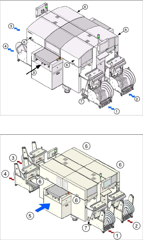
Button for docking and undocking changeover tables
(D4)
Legend
1. Changeover table location 1
2. Changeover table location 2
3. Changeover table location 3
4. Changeover table location 4
5. Transport direction
6. The button for docking and undocking the changeo-
ver tables is located under the feeder cover flap of
each changeover table
7. Switch to lower the table after undocking/docking
Button for docking and undocking changeover tables
(D4i)
1.