00195440-05-SG_D-Series_FSE-EN.pdf - 第39页
3 Overview 3.4.7 C&P12 Head DLM3 3.4 Assemblies Student Guide SIPLACE D-Series (FSE) 39 Overview of standard feeders 3.4.7 3 . 4 . 7 C & P 1 2 H e a d D L M 3 C&P12 Head DLM3 3.4.7.1 3 . 4 . 7 . 1 G e n e r a…
3 Overview
3.4 Assemblies 3.4.6 Changeover Table Components
38 Student Guide SIPLACE D-Series (FSE)
3.4.6
3.4.6 Changeover Table Components
Changeover Table Components
3.4.6.1
3.4.6.1 Overview of S-Feeder
Overview of S-Feeder
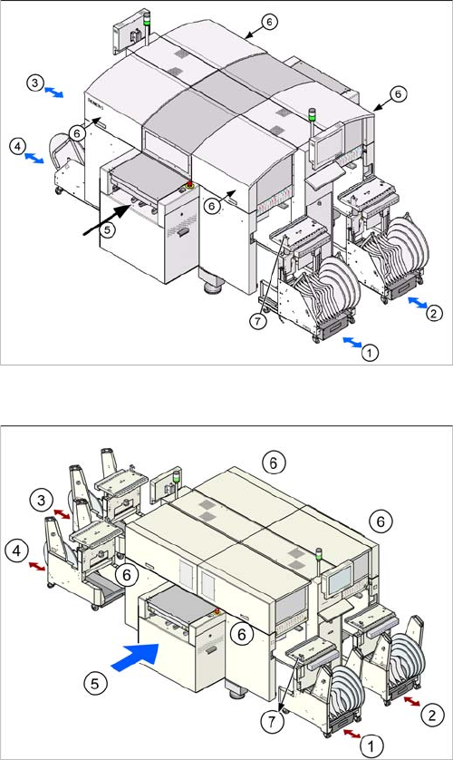
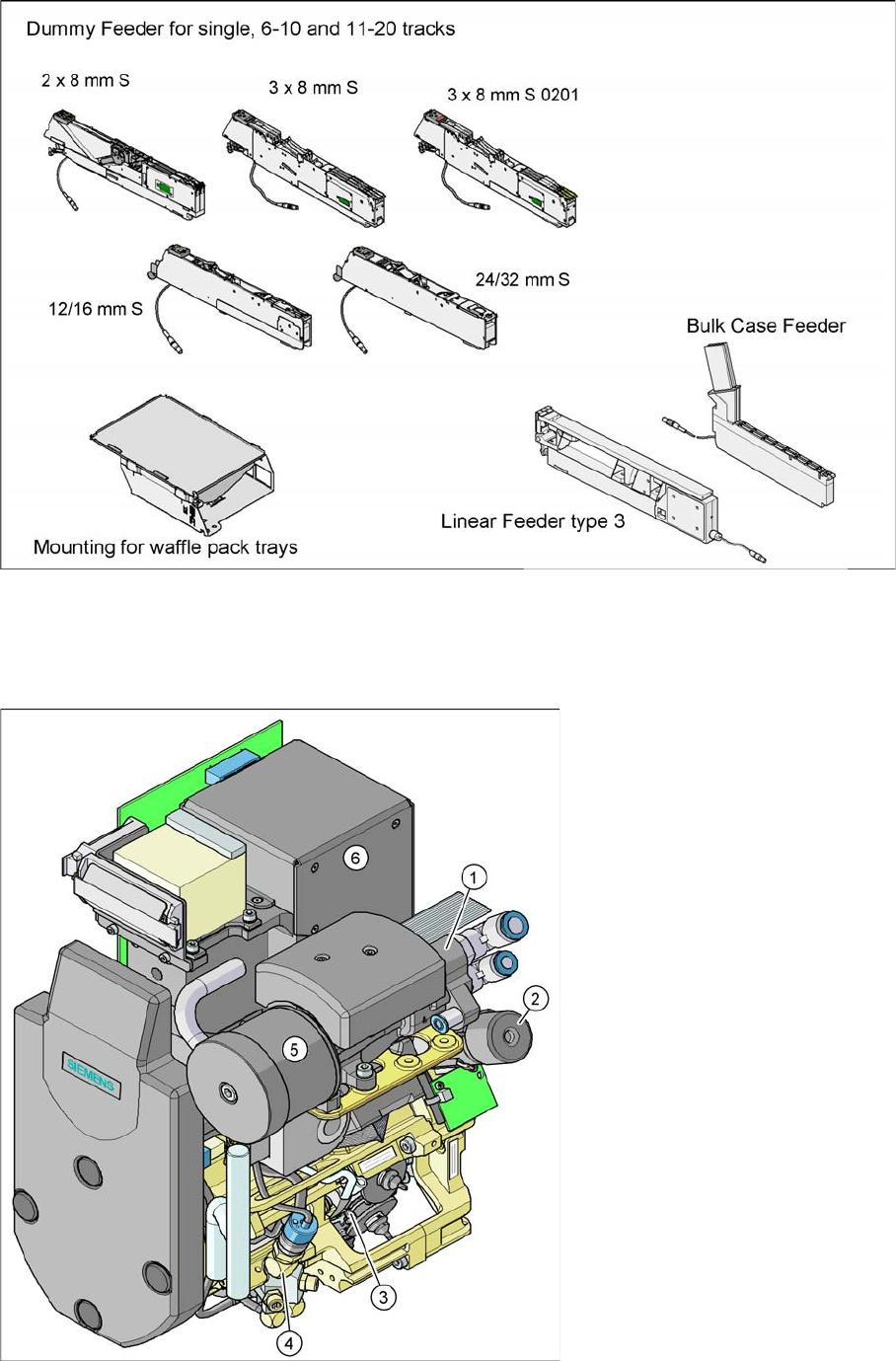
Description: 9 different feeders are enough to process tapes with widths from 8 to 88 mm. The tape reels
on the feeder are taken up by the component trolley tape container. The cutter then cuts up the empty
tape automatically. SIPLACE feeders are known for their short cycle times and highly accurate pickup
positions.
These feeders can also be used in other SIPLACE placement machines.
In addition to the tape feeders, bulkcase feeders, linear feeders, surftape feeders, Dipflux modules, com-
ponent reject conveyors and manual trays can also be used. If a location is not occupied, a so-called
dummy feeder is inserted for safety purposes.
Button for docking and undocking changeover tables
(D4)
Legend
1. Changeover table location 1
2. Changeover table location 2
3. Changeover table location 3
4. Changeover table location 4
5. Transport direction
6. The button for docking and undocking the changeo-
ver tables is located under the feeder cover flap of
each changeover table
7. Switch to lower the table after undocking/docking
Button for docking and undocking changeover tables
(D4i)
1.
3 Overview
3.4.7 C&P12 Head DLM3 3.4 Assemblies
Student Guide SIPLACE D-Series (FSE) 39
Overview of standard feeders
3.4.7
3.4.7 C&P12 Head DLM3
C&P12 Head DLM3
3.4.7.1
3.4.7.1 General
General
C&P12 Head DLM3
3 Overview
3.4 Assemblies 3.4.7 C&P12 Head DLM3
40 Student Guide SIPLACE D-Series (FSE)
Legend
Option: Digital camera SST.29 for the C&P12 head and component sensor [00118021-xx] for 0201
placement.
Note: Digital camera SST30 will replace SST29 in C&P12 head for D4i and SST29 in C&P6 head for
D1i/D2i
3.4.7.2
3.4.7.2 Overview of Functions for Star Stations 1-12
Overview of Functions for Star Stations 1 - 12
3.4.7.3
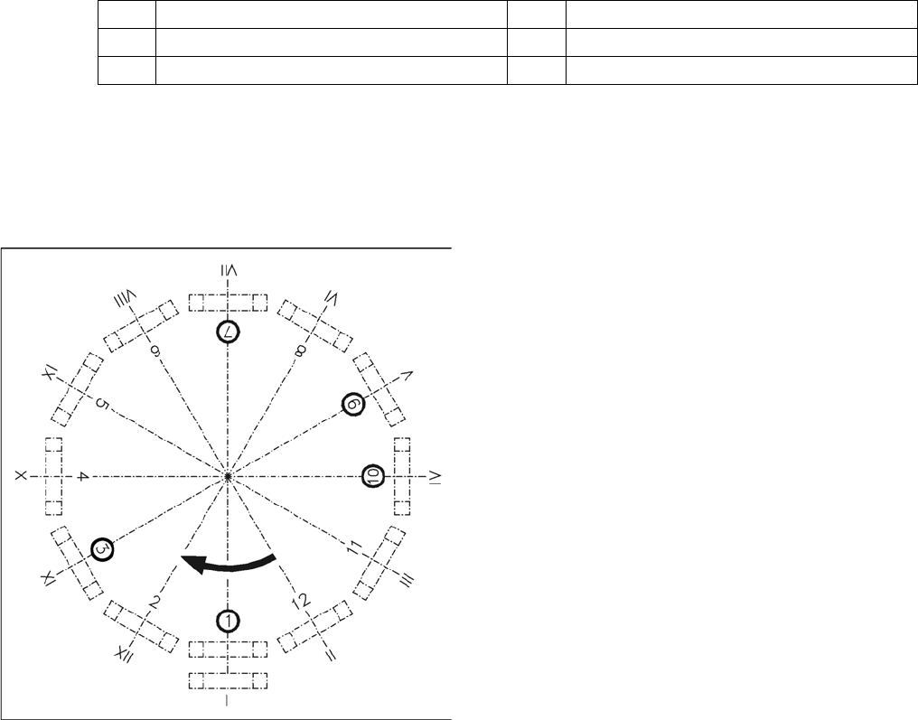
3.4.7.3 Position and Function of the Individual Star Stations
Position and Function of the Individual Star Stations
Star station 1:
▪ Pickup cycle
The nozzle is lowered towards the component. After a vacuum has been produced with the help of
the valve positioning function, the nozzle takes the component from the feeder module.
▪ Placement cycle
The nozzle, together with the component, is lowered onto the PCB that has been moved into place.
The valve is positioned to cut off the supply of vacuum to the nozzle. A brief burst of air separates
the component from the nozzle and the component is placed onto the board.
Star station 3:
▪ Abwurfzyklus bei D4/D4i/D3/D2/D2i
(Bei D1/D1i wird in Sternstation 1 in den P&P-Abwurfbehälter abgeworfen)
The valve is positioned to cut off the supply of vacuum to the nozzle. Defective components are re-
jected from the nozzle with a short air blast of compressed air and are discarded.
Star station 7:
▪ The component is optically centered.
1 Vacuum generator 4 Air blast valve
2 Turning station (DP axis) 5 Silencer
3 Star with 12 sleeves (star axis) 6 Component Camera
Overview of functions for star stations 1 - 12
Star station 1: pickup, placement
Star station 2: no function
Star station 3: reject component
Star station 4-6: no function
Star station 7: optical centering of component
Star station 8: no function
Star station 9: rotate component
Star station 10: service position for sleeves and nozzles
Star station 11 and 12: no function (optional component
sensor)
I - XII: Segment numbering