00195440-05-SG_D-Series_FSE-EN.pdf - 第70页
4 Communication and Control 4.3 CAN Bus 4.3.8 Communication Siplace Vision 70 Student Guide SIPLACE D-Series (FSE) 4.3.8 4 . 3 . 8 C o m m u n ic a t io n S ip la c e V is io n Communication Siplace Vision Overview Sipla…

4 Communication and Control
4.3.7 File Name Codes for Downloading 4.3 CAN Bus
Student Guide SIPLACE D-Series (FSE) 69
*
Only for X machines equipped with C&P20 head
R0100208.bh
x
R means axis controller D-axis TWIN
S0100208.bh
x
S means star axis C&P12/6
T0100302.he
x
T means conveyor control (note the HW version)
T01xxxxx.he
x
Conveyor HS 50 with TSP 100 control
T02xxxxx.he
x
Conveyor HS 50 with TSP 200 control
T03xxxxx.he
x
Conveyor control S25HM/F5HM
T04xxxxx.he
x
Conveyor control S27/D1/2/D1i/2i with TSP 201
T05xxxxx.he
x
Conveyor control HS 60/D4/D4i with TSP301
T06xxxxx.he
x
Conveyor control X-machines/D3 with TSP 301
U…… U …. 2nd download level creates a 2nd letter in name.
UA100208.b
hx
A .1.02.08 UA means X-feeder controller SW
UB0100208.
bhx
B .1.02.09 UB means X adapter for special feeders on X tables
V0500208.bh
x
V means Vision controller subboards for head and stationary cameras
V01… V04 ... Integrated in K01 to K04xxxxx.bhx (8 bit CAN controller)
V0500208.bh
x
Vision CAN controller for head and stationary cameras since HF
machines
W0100208.b
hx
* W
means Z-axis C&P20
X0100208.bh
x
X means X-axes
Y0100208.bh
x
Y means Y-axes
Z0100208.bh
x
Z means Z-axes C&P12/6
File name Other descrip-
tion
HW components as letters
HW version details
4 Communication and Control
4.3 CAN Bus 4.3.8 Communication Siplace Vision
70 Student Guide SIPLACE D-Series (FSE)
4.3.8
4.3.8 Communication Siplace Vision
Communication Siplace Vision
Overview Siplace Vision
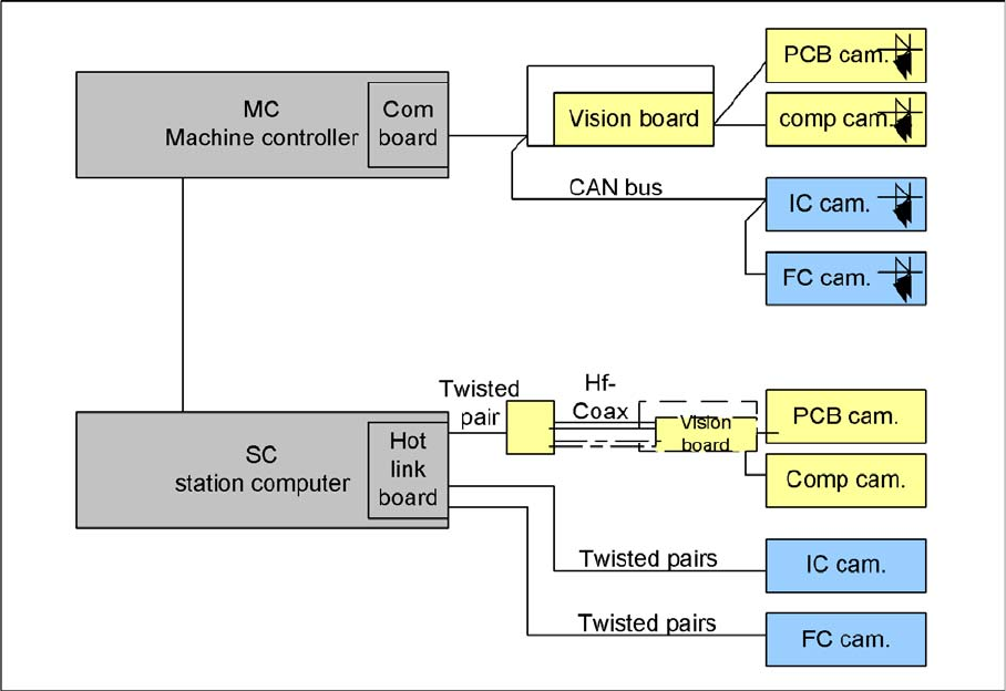
The communication between the computers is carried out via LAN cables. The MC sends the commands
for the image acquisition to the vision computer and receives the result of the measuring. The MC also
sends the illumination values for the corresponding CSs. The pictures taken are sent digitally via the Hot
link card to the Vision task of the station computer, where they are evaluated. The result of this evalua-
tion (X/Y angle coordinates, good/bad state) is sent to the MC.
4 Communication and Control
4.3.9 CAN Bus Processor Board on the Gantry Head Distributor 4.3 CAN Bus
Student Guide SIPLACE D-Series (FSE) 71
4.3.8.1
4.3.8.1 Communication During Image Acquisition
Communication During Image Acquisition
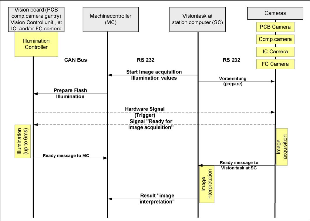
Time sequence from up to down for the communication image acquisition
The main communication between the vision system and machine controller is the transmission of illu-
mination values. These values, stored in the component shape, are sent via the CAN bus to the camera
concerned. When the camera is needed to take a picture, it will be activated by a trigger signal. From
this moment on the row of LEDs which provide the different illumination levels light dependent on the
illumination value 0-255. This illumination value can have 0 = dark up to 255 = bright. The length of the
illumination period is set by using a value between 0 and 255.
The maximum length of illumination is limited to 6 ms.
4.3.9
4.3.9 CAN Bus Processor Board on the Gantry Head Distributor
CAN Bus Processor Board on the Gantry Head Distributor
The TQM 167LC CAN bus processor board is connected to the head board. The processor board is used
at different places in the machine. If the processor board on the head board, the firmware provides at
the processor board the control of the head specific actuators and sensors no matter which head type is
installed.
4.3.9.1
4.3.9.1 CAN BUS-Controlled Functions on the C&P12 Head
CAN BUS-Controlled Functions on the C&P12 Head
The following overview shows various head functions, controlled by the CAN system. Thus, the CAN bus
controls the actuators and sensors of the C&P head.