00195440-05-SG_D-Series_FSE-EN.pdf - 第72页
4 Communication and Control 4.3 CAN Bus 4.3.10 CAN Bus Communication with Axis Controller 72 Student Guide SIPLACE D-Series (FSE) CAN function on C&P head 4.3.10 4 . 3 . 1 0 C A N B u s C o m m u n ic a t io n w it h…
4 Communication and Control
4.3.9 CAN Bus Processor Board on the Gantry Head Distributor 4.3 CAN Bus
Student Guide SIPLACE D-Series (FSE) 71
4.3.8.1
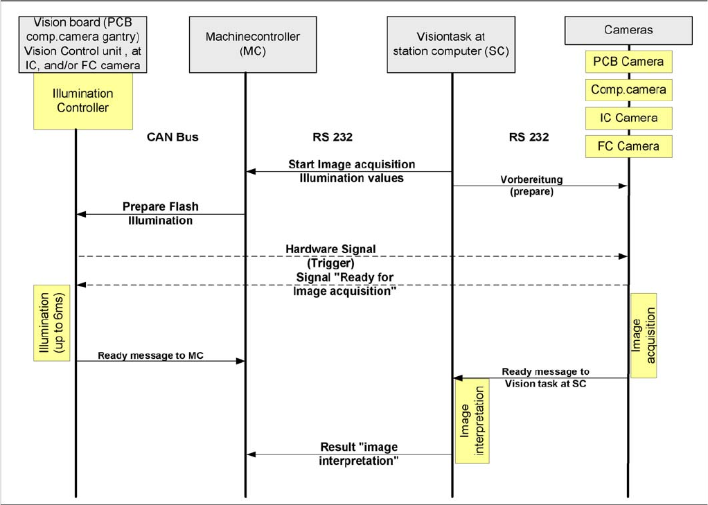
4.3.8.1 Communication During Image Acquisition
Communication During Image Acquisition
Time sequence from up to down for the communication image acquisition
The main communication between the vision system and machine controller is the transmission of illu-
mination values. These values, stored in the component shape, are sent via the CAN bus to the camera
concerned. When the camera is needed to take a picture, it will be activated by a trigger signal. From
this moment on the row of LEDs which provide the different illumination levels light dependent on the
illumination value 0-255. This illumination value can have 0 = dark up to 255 = bright. The length of the
illumination period is set by using a value between 0 and 255.
The maximum length of illumination is limited to 6 ms.
4.3.9
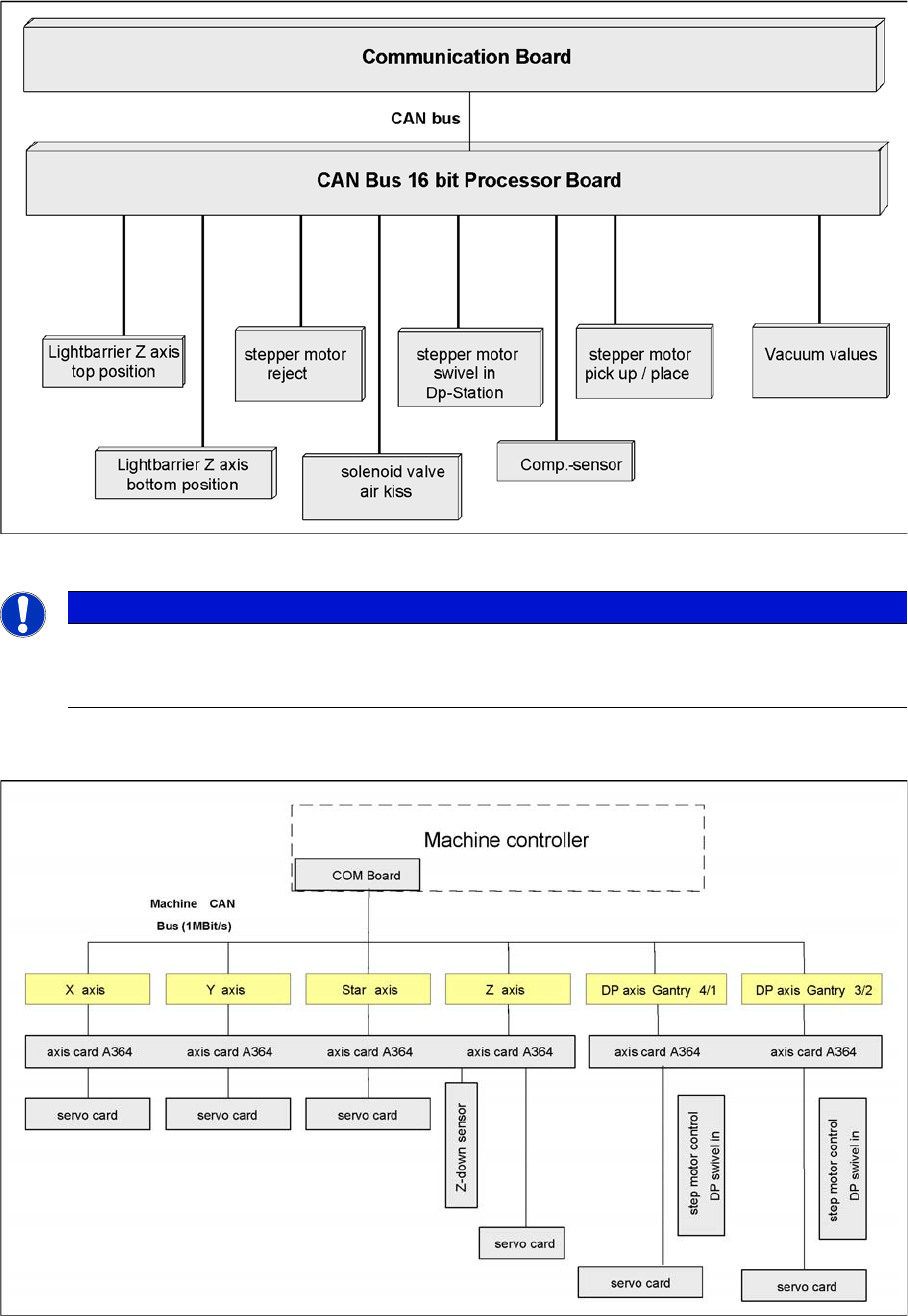
4.3.9 CAN Bus Processor Board on the Gantry Head Distributor
CAN Bus Processor Board on the Gantry Head Distributor
The TQM 167LC CAN bus processor board is connected to the head board. The processor board is used
at different places in the machine. If the processor board on the head board, the firmware provides at
the processor board the control of the head specific actuators and sensors no matter which head type is
installed.
4.3.9.1
4.3.9.1 CAN BUS-Controlled Functions on the C&P12 Head
CAN BUS-Controlled Functions on the C&P12 Head
The following overview shows various head functions, controlled by the CAN system. Thus, the CAN bus
controls the actuators and sensors of the C&P head.
4 Communication and Control
4.3 CAN Bus 4.3.10 CAN Bus Communication with Axis Controller
72 Student Guide SIPLACE D-Series (FSE)
CAN function on C&P head
4.3.10
4.3.10 CAN Bus Communication with Axis Controller
CAN Bus Communication with Axis Controller
Overview axis controller
In previous Siplace placement machines, the communication and data flow between axis controller and
machine controller was achieved using the SMP bus. From the HF machine generation onwards, the
SMP bus is no longer used with the axis system.
NOTICE
The status of the 16 Bit PROCESSOR BOARD is indicated on the 7-segment display.
Normal status on the display is: Display shows slowly flashed " . (for description see Section
C&P12).
4 Communication and Control
4.3.10 CAN Bus Communication with Axis Controller 4.3 CAN Bus
Student Guide SIPLACE D-Series (FSE) 73
The communication between the axis controller modules is now achieved using the CAN Bus. All the
information exchanged between these modules is transmitted via the CAN bus (e.g. axis parameters,
target position, end position signal ...). This means that the number of individual telegrams increases sig-
nificantly over time, compared to the amount of data in older machine generations.
The axis control system is divided into:
▪ Axis control I and II for gantry and main axes, plus
▪ Axis control III for "remaining head axes".
Axis control I and II communicate directly with one another, via the interrupt lines for the anti-crash mon-
itoring system. The data communicated is the two Y gantry axis positions and the axis states.