00195440-05-SG_D-Series_FSE-EN.pdf - 第77页
5 Energy and Compressed Air Supply 5.1 Overview Student Guide SIPLACE D-Series (FSE) 77 5 5 E n e r g y a n d C o m p r e s s e d A ir S u p p ly Energy and Compressed Air Supply 5.1 5 . 1 O v e r v ie w Overview The dia…
4 Communication and Control
4.4 Room for Your Sketches and Notes 4.3.10 CAN Bus Communication with Axis Controller
76 Student Guide SIPLACE D-Series (FSE)
5 Energy and Compressed Air Supply
5.1 Overview
Student Guide SIPLACE D-Series (FSE) 77
5
5 Energy and Compressed Air Supply
Energy and Compressed Air Supply
5.1
5.1 Overview
Overview
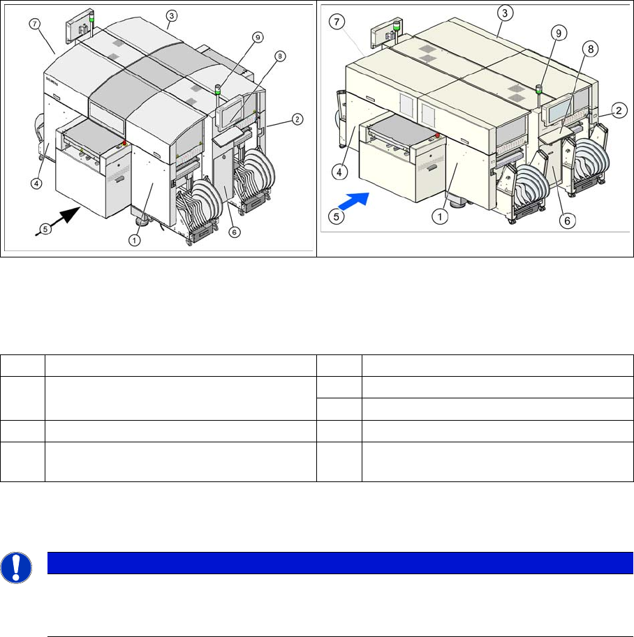
The diagram shows where the energy supplying and distributing components for system operation are
installed:
Legend
5.2
5.2 Power Supply Unit
Power Supply Unit
1 Sector distributor for sector 1 5 Transport direction
2 Sector distributor for sector 2 (only by D4
on the back of the machine)
6 Pneumatic Unit
7 Power Supply Unit
3 Sector distributor for sector 3 8 Controls (keyboard and monitor)
4 Sector distributor for sector 4 (this area is
sector 2 in D1/D2 or D1i/D2i)
9 Error display (right-hand machine side)
NOTICE
Cause of Hazard
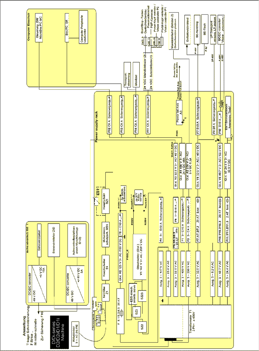
Unless otherwise specified, the wiring examples shown in this section apply for SIPLACE D4/
D4i machines. Refer to the relevant circuit diagrams for all other machine types.
5 Energy and Compressed Air Supply
5.2 Power Supply Unit 5.2.1 Overview of Power Supply
78 Student Guide SIPLACE D-Series (FSE)
5.2.1
5.2.1 Overview of Power Supply
Overview of Power Supply
5.2.1.1
5.2.1.1 Overview of Power Supply D1/D1i/D2/D2i
Overview of Power Supply D1/D1i/D2/D2i