00195440-05-SG_D-Series_FSE-EN.pdf - 第80页
5 Energy and Compressed Air Supply 5.2 Power Supply Unit 5.2.2 Overview of Power Supply 80 Student Guide SIPLACE D-Series (FSE) 5.2.1.3 5 . 2 . 1 . 3 O v e r v ie w o f P o w e r S u p p ly D 4 / D 4 i Overview of Power …
5 Energy and Compressed Air Supply
5.2.1 Overview of Power Supply 5.2 Power Supply Unit
Student Guide SIPLACE D-Series (FSE) 79
5.2.1.2
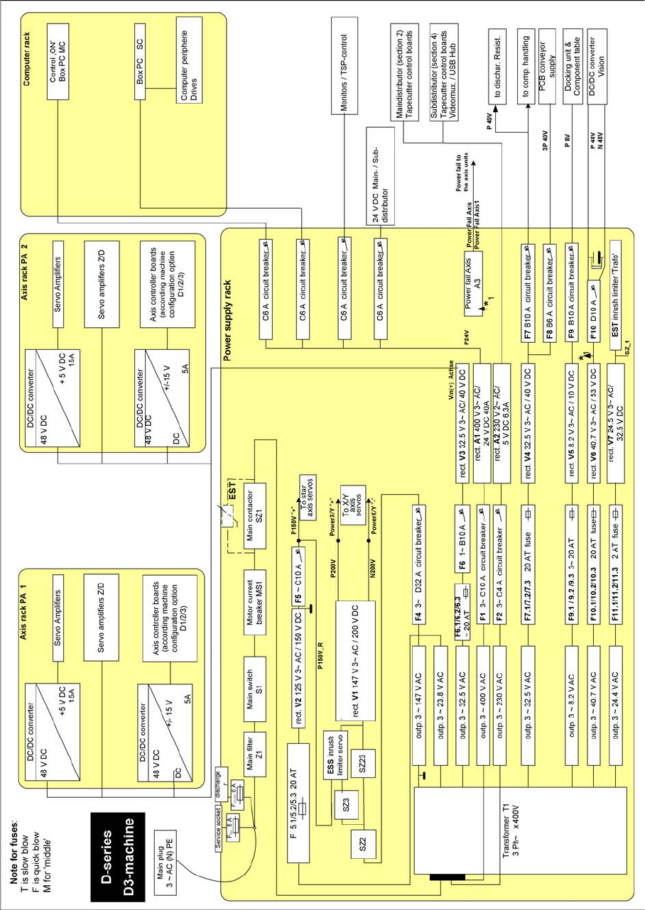
5.2.1.2 Overview of Power Supply D3
Overview of Power Supply D3
5 Energy and Compressed Air Supply
5.2 Power Supply Unit 5.2.2 Overview of Power Supply
80 Student Guide SIPLACE D-Series (FSE)
5.2.1.3
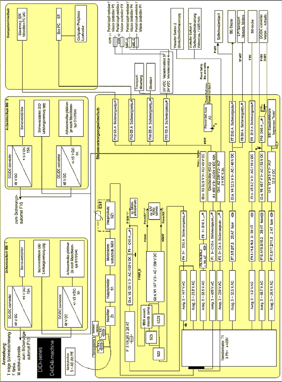
5.2.1.3 Overview of Power Supply D4/D4i
Overview of Power Supply D4/D4i
5.2.2
5.2.2 Overview of Power Supply
Overview of Power Supply
The main power supply unit is mounted on a compact slide-in module, and located on the left side of the
middle section. When viewed from the outside only the red main power switch is visible.
A lockable door prevents access to the power supply.
5 Energy and Compressed Air Supply
5.2.2 Overview of Power Supply 5.2 Power Supply Unit
Student Guide SIPLACE D-Series (FSE) 81
With the open cover, the state of the following protective devices can be quite easily monitored.
▪ Motor protection switch
▪ main contactor
▪ Safety relay
▪ Power circuit breaker
The following work must be performed to adjust the power supply to the country-specific requirements
(see also the conversion instructions for 3x 208 V to 3x 400 V and vice versa):
► Rewiring line supply cable/transformer
► Motor protecting switch
► Inrush current limiter connections
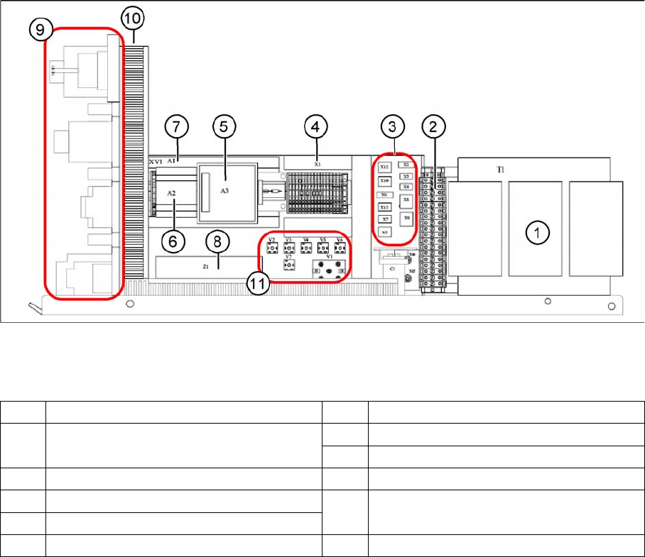
Main power supply - side view
Legend
1 Transformer 1 7 Power supply A1 (24 V/40 A)
2 Secondary terminal strip with fuses (output
voltage T1)
8 Line filter Z1 (input voltage)
8 Line filter Z1 (input voltage)
3 Connector strip X2-X10, X12, X13 9 Front view (see following diagram)
4 Terminal strip X1 10 Inrush current limiter (behind the cable
duct)
5 Power fail board A3
6 Power supply A2 (5 V/6.3 A) 11 Various rectifiers (V5 not in D1/D2/D1i/D2i)