00195440-05-SG_D-Series_FSE-EN.pdf - 第82页
5 Energy and Compressed Air Supply 5.2 Power Supply Unit 5.2.2 Overview of Power Supply 82 Student Guide SIPLACE D-Series (FSE) Main power supply – front view (D4/D4i) Legend 1. F1 : 3x 230 V AC SZ1 : main contactor MS1 …
5 Energy and Compressed Air Supply
5.2.2 Overview of Power Supply 5.2 Power Supply Unit
Student Guide SIPLACE D-Series (FSE) 81
With the open cover, the state of the following protective devices can be quite easily monitored.
▪ Motor protection switch
▪ main contactor
▪ Safety relay
▪ Power circuit breaker
The following work must be performed to adjust the power supply to the country-specific requirements
(see also the conversion instructions for 3x 208 V to 3x 400 V and vice versa):
► Rewiring line supply cable/transformer
► Motor protecting switch
► Inrush current limiter connections
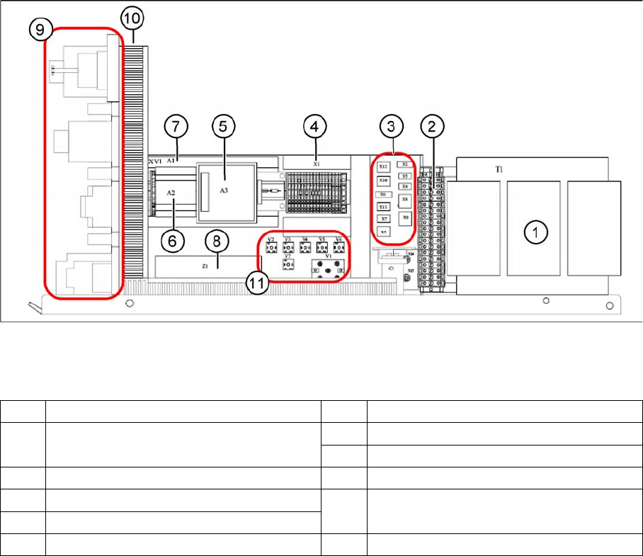
Main power supply - side view
Legend
1 Transformer 1 7 Power supply A1 (24 V/40 A)
2 Secondary terminal strip with fuses (output
voltage T1)
8 Line filter Z1 (input voltage)
8 Line filter Z1 (input voltage)
3 Connector strip X2-X10, X12, X13 9 Front view (see following diagram)
4 Terminal strip X1 10 Inrush current limiter (behind the cable
duct)
5 Power fail board A3
6 Power supply A2 (5 V/6.3 A) 11 Various rectifiers (V5 not in D1/D2/D1i/D2i)
5 Energy and Compressed Air Supply
5.2 Power Supply Unit 5.2.2 Overview of Power Supply
82 Student Guide SIPLACE D-Series (FSE)
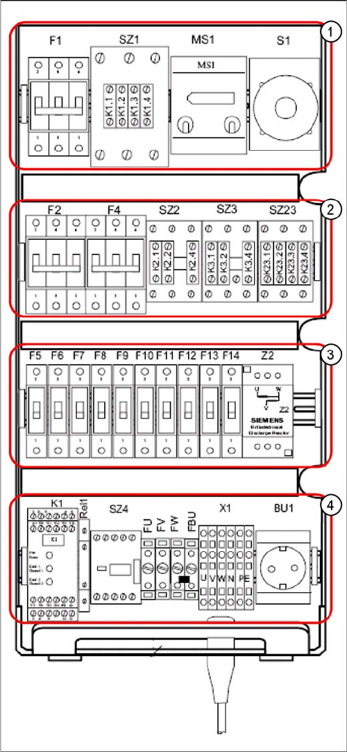
Main power supply – front view (D4/D4i)
Legend
1. F1: 3x 230 V AC
SZ1: main contactor
MS1: Motor protection switch
S1: main switch
2. F2: 220 V AC for 5 V power supply
F4: 3x 140 VAC X/Y axes
SZ2,SZ3, SZ23: auxiliary contactors U,V,W for X/Y
servos
3. F5: 150 V DC star axis servo
F6: 40 V DC Z/DP axis servo
F7: 40 V DC changeover table
F8: 40 V DC PCB handling (conveyor)
F9: 8 V DC changeover table (only at D4/D4i)
F10: 48 V DC Vision illumination
F11: 24 V DC terminal strip distributor 2/4
F12: 24 V DC Microbox PC (MC)/control "ON" (K1)
F13: 24 V DC Box PC (SR)/axis unit 1/2
F14: 24 V DC conveyor control (TSP 301)/monitors
Z2: discharge inductor
4. K1: protective contactor combination
Relay1: control ON - button
SZ4: control ON - software
FU: fuse 6.3 AT 220 VAC to GND
FV: fuse 6.3 AT 220 VAC to GND
FW: fuse 6.3 AT 220 VAC to GND
FBU: fuse 6.3 AT 220 VAC to GND
X1: feed in - terminal strip
BU1: service socket
5 Energy and Compressed Air Supply
5.2.3 Input Voltage 5.2 Power Supply Unit
Student Guide SIPLACE D-Series (FSE) 83
5.2.3
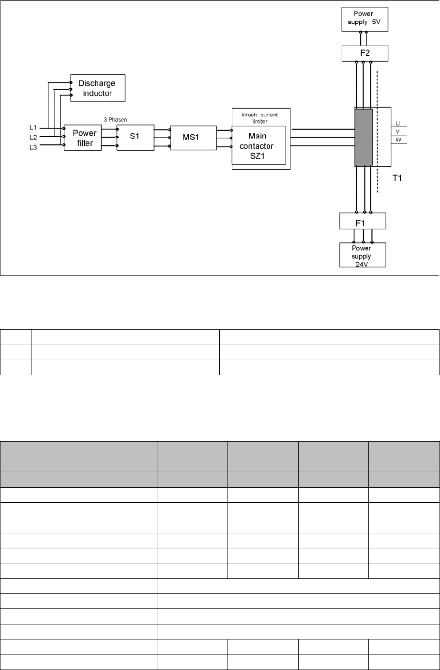
5.2.3 Input Voltage
Input Voltage
Input voltage
Legend
5.2.4
5.2.4 Naming Convention of Connectors and Cables
Naming Convention of Connectors and Cables
The SIPLACE basic machine cables and leads are clearly labeled. Each cable, connector, distributor
uses an exact term, which is dedicated to the sections and units in question.
S1 Main switch F1 Fuse for 24 V power pack
MS1 Motor protection switch F2 Fuse for 5 V power pack
SZ1 Main contactor and inrush current limiter
Machine type: D1/D2/D3/D4/
D1i/D2i/D4i
--/D2/--/D4/-/
D2i/-/D4i
--/--/D3/D4/
--/-/D4i
--/--/D3/D4/
--/--/D4i
Placement head for Gantry 1 Gantry 2 Gantry 3 Gantry 4
Designation a+ b+ c+ d+
Trailing cable distributor 03035887 aa ba ca da
Gantry distributor 03035888 ab bb cb db
Gantry head distributor 03038002 ac bc cc dc
Vision board eu fu gu hu
Hotlink filter lf mf nf of
SC Always pc
Hotlink card pr
MC Always pa
USB hub pd
Sector 1 af af af af
Sector 2 (output side) bf bf (left) bf bf