00195440-05-SG_D-Series_FSE-EN.pdf - 第85页
5 Energy and Compressed Air Supply 5.2.6 Assemblies in Sector 2 5.2 Power Supp ly Unit Student Guide SIPLACE D-Series (FSE) 85 5.2.6 5 . 2 . 6 A s s e m b lie s in S e c t o r 2 Assemblies in Sector 2 Assembly in sector …
5 Energy and Compressed Air Supply
5.2 Power Supply Unit 5.2.5 Assemblies in Sector 1
84 Student Guide SIPLACE D-Series (FSE)
5.2.5
5.2.5 Assemblies in Sector 1
Assemblies in Sector 1
Sector 3 (output side) cf cf -- --
Sector 4 df df -- --
Subassemblies in the sector distributors have other designations, which may also differ between the
machine types.
Machine type: D1/D2/D3/D4/
D1i/D2i/D4i
--/D2/--/D4/-/
D2i/-/D4i
--/--/D3/D4/
--/-/D4i
--/--/D3/D4/
--/--/D4i
Placement head for Gantry 1 Gantry 2 Gantry 3 Gantry 4
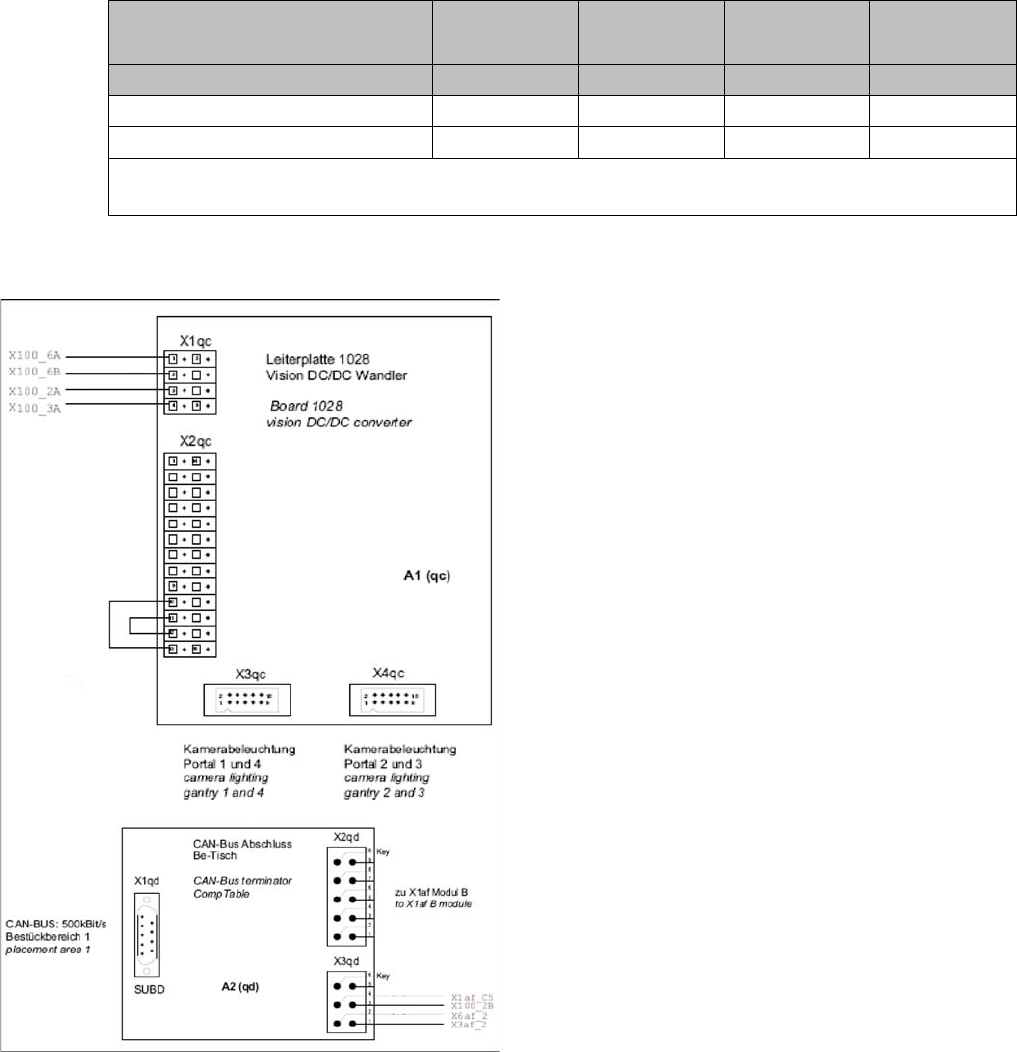
Naming convention for cables and connections in sector
1
▪ Conveyor control ao (D1/D2/D1i/D2i: kc)
▪ Terminal strip (voltage supply) X100
▪ Connections (plug-in connectors) af
▪ Vision DC/DC converter A1 qc
▪ CAN Bus terminator for changeover table qd
In D1/D2/D1i/D2i, the subassemblies and the main dis-
tributor are marked with r...
The designations are as follows:
▪ A3 CAN bus terminator connection for changeover
table: rb
▪ A3 CAN bus terminator connection for WPC: rd
▪ Vision DC/DC converter assembly: rc
▪ The conveyor assembly TSP201 also has the con-
nector and lead designation ao.
5 Energy and Compressed Air Supply
5.2.6 Assemblies in Sector 2 5.2 Power Supply Unit
Student Guide SIPLACE D-Series (FSE) 85
5.2.6
5.2.6 Assemblies in Sector 2
Assemblies in Sector 2
Assembly in sector 2 (D4/D4i shown as example, diagram rotated by 90° to left; some of the connectors are not
present in D1/D2/D1i/D2i)
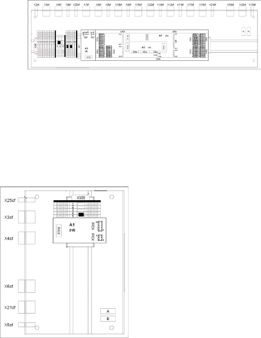
Naming convention for cables and connections in sector 2
▪ Terminal strip (voltage supply) X200
▪ Connections (plug-in connectors) bf
▪ CAN I/O module qc (assembly A1)
▪ CAN interface re (assembly A2)
▪ CAN Bus board for changeover table rf (assembly A3)
In D1/D2/D1i/D2i machines, the following subdistributor designations apply for the subassemblies:
▪ A3: qf
▪ A2: qe
5.2.7
5.2.7 Assemblies in Sector 3
Assemblies in Sector 3
Naming convention for cables and connections in sector
3
▪ Terminal strip (voltage supply) X300
▪ Connections (plug-in connectors) cf
▪ CAN Bus terminator for changeover table rd
5 Energy and Compressed Air Supply
5.2 Power Supply Unit 5.2.8 Assemblies in Sector 4
86 Student Guide SIPLACE D-Series (FSE)
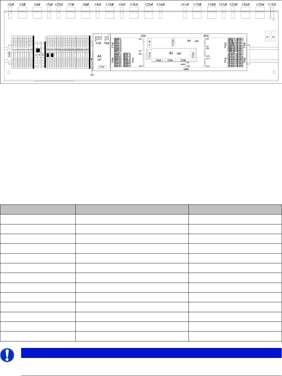
5.2.8
5.2.8 Assemblies in Sector 4
Assemblies in Sector 4
(diagram rotated by 90°)
Naming convention for cables and connections in sector 4
▪ Terminal strip (voltage supply) X400
▪ Connections (plug-in connectors) df
▪ CAN I/O module qb
▪ CAN interface qe
▪ CAN Bus terminator for changeover table qf
5.2.9
5.2.9 Voltages in the Power Supply Unit After Switching On
Voltages in the Power Supply Unit After Switching On
When the main switch is activated, the following voltages are generated, sent to the modules and re-
leased or held ready for release:
Voltages Module State
250 VDC X/Y servo module not enabled
150 VDC Star servo not enabled
34 VDC PCB handling system Released up to SZ2
24 VDC Tape cutter not enabled
34 VDC SZ1 main power inrush current enabled
52 VDC DC/DC converter main power supply enabled
52 VDC Camera illumination enabled
40 VDC Power fail A3 enabled
42 V DC Z/DP axes enabled
40 VDC Feeder table plate enabled
28 VDC Monitor enabled
24 VDC fan enabled
230 or 115 or 240 VAC service socket independent of the main switch
NOTICE
The service socket can only be used if the placement system is connected to the main power
supply with a 5-conductor cable (L1, L2, L3, N, PE).