00195440-05-SG_D-Series_FSE-EN.pdf - 第88页
5 Energy and Compressed Air Supply 5.3 Pneumatic System 5.3.1 Vac uum Generation at C&P Heads - Gene ral Information 88 Student Guide SIPLACE D-Series (FSE) The vent uri block actu ally consists of 2 separat e ventur…
5 Energy and Compressed Air Supply
5.2.10 Power Supply for Axis Unit 5.3 Pneumatic System
Student Guide SIPLACE D-Series (FSE) 87
5.2.10
5.2.10 Power Supply for Axis Unit
Power Supply for Axis Unit
5.3
5.3 Pneumatic System
Pneumatic System
5.3.1
5.3.1 Vacuum Generation at C&P Heads - General Information
Vacuum Generation at C&P Heads - General Information
The air is supplied to the vacuum generator, which produces a vacuum using the venturi principle.
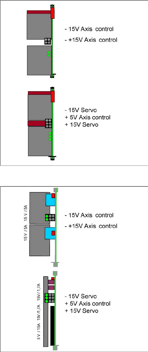
Power supply for axis unit (new version)
After activating the main switch, the axis unit is supplied
with power from the main power supply, via X8 for axis
unit 1 and X9 for axis unit 2. It is supplied with 48 VDC
and the following voltages are generated:
▪ +/-15 V and +/-15/5 V
This DC/DC converter generates the 5V and +/- 15V
needed for the servo board and the axis controller
Power supply for axis unit (old version)
5 Energy and Compressed Air Supply
5.3 Pneumatic System 5.3.1 Vacuum Generation at C&P Heads - General Information
88 Student Guide SIPLACE D-Series (FSE)
The venturi block actually consists of 2 separate venturi nozzles which produce vacuum for 2 circuits,
the holding circuit and the pick up / placement circuit.
The level of vacuum produced is dependent on a number of factors. The greatest influence on vacuum
generation is from the Venturi unit. Any leakage from or blockage within the system will result in working
inefficiently and therefore a reduction in the vacuum levels created. The Venturi unit must be absolutely
airtight and the nozzles in very good condition and of high quality.
One factor which can impair vacuum generation is the altitude. The higher above sea level a machine is
located, the low the ambient pressure will be in the room surrounding it. Therefore at high altitude low
vacuum levels are created, A SIPLACE machine in Munich, at an altitude of 500 m above sea level, can
generate a closed vacuum of approx. 870 mbar, while a machine at sea level in England would be able
to produce approx. 920 mbar.
Another factor influencing the vacuum values is the weather. Stormy, rainy days occur in periods of low
pressure. Vacuum generation during this weather may produce 880 mbar, while the same procedure a
week later, on a sunny day in a high pressure period, could well produce closed vacuum results of 900
mbar.
These 2 cases are only examples and no specific case / figures are used, but this just illustrates what
can happen. In any case, it is important that you use an efficient, high quality vacuum system.
The vacuum measurement board is located directly above the vacuum generator and measures the vac-
uum values in the hold and pickup/placement circuits. Small tubes are attached to the back of the Collect
& Place head that measure the circuit pressures at the vacuum distributor. These tubes are connected
to pressure sensors. The analogue outputs of these sensors are supplied to A/D converters. The result-
ing signals are then sent via the CAN-Bus to the machine controller.
5 Energy and Compressed Air Supply
5.3.2 Overview Pneumatic System 5.3 Pneumatic System
Student Guide SIPLACE D-Series (FSE) 89
5.3.2
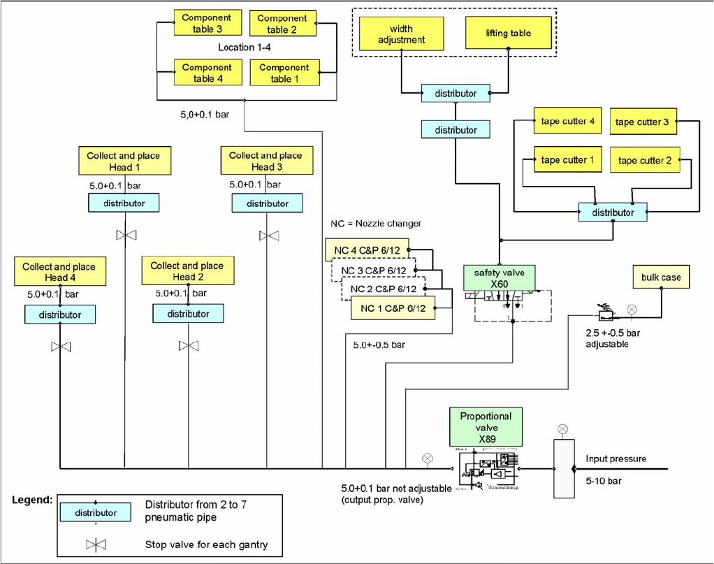
5.3.2 Overview Pneumatic System
Overview Pneumatic System
Overview of pneumatic system/compressed air supply (D4/D4i)