00195440-05-SG_D-Series_FSE-EN.pdf - 第97页
6 Reference Run 6.1.1 Overview 6.1 Refere nce Run (D/Di-Series) Student Guide SIPLACE D-Series (FSE) 97 6 6 R e f e r e n c e R u n Reference Run 6.1 6 . 1 R e f e r e n c e R u n ( D / D i- S e r ie s ) Reference Run (D…

5 Energy and Compressed Air Supply
5.4 Room for Your Sketches and Notes 5.3.5 Bulk Case System
96 Student Guide SIPLACE D-Series (FSE)
6 Reference Run
6.1.1 Overview 6.1 Reference Run (D/Di-Series)
Student Guide SIPLACE D-Series (FSE) 97
6
6 Reference Run
Reference Run
6.1
6.1 Reference Run (D/Di-Series)
Reference Run (D/Di-Series)
The placement machine reference run guaranties the correct function for placement in the station SW.
In diesem Kapitel wird der Referenzlauf für C&P-Kopf und Portal beschrieben. Danach wird der parallel
zum C&P-Kopf ausgeführte Referenzlauf zum P&P-Modul beschrieben.
6.1.1
6.1.1 Overview
Overview
The reference run is divided into 4 main steps. Module reference runs for the WPC or for a 2nd place-
ment head per gantry are not listed at this stage.
1. Conveyor system reference run
This activates the unoccupied (not occupied with a PCB) conveyors.
(in older SW versions, this function can also be performed to conclude the reference run.)
2. Axis reference run
This is divided into:
A.) the head axis reference run and
B.) the gantry axis reference run.
The gantry head axes are started at the same time. As many functions as possible are performed at
the same time.
3. Vacuum reference run
The
A.) vacuum values "open" and "closed" for placement are determined and
B.) all segments in the DP stations are rotated into their 0 degrees positions.
4. Height reference run
This function tests the length of the segment nozzles and of the heads in a placement area, on the
top surface of a conveyor side.
These are described and explained in detail below. Machine type or configuration-related extensions or
deviations are explained in separate texts to prevent confusion.
6.1.2
6.1.2 Conveyor Reference Run
Conveyor Reference Run
The conveyor reference run tests the function of the conveyor belts. This requires the relevant conveyor
belt to be empty i.e. to be free of boards (PCB). Stellt einer der LP-Sensoren eine LP fest so wird dieses
Transportband (so wie auch das Eingabe-Transportband) nicht aktiviert und am Ende des gesamten
Referenzablaufes wird diese LP in das Ausgabeband der Bestückstation transportiert.
6.1.3
6.1.3 Axis Reference Run
Axis Reference Run
6.1.3.1
6.1.3.1 Head Axis Reference Run
Head Axis Reference Run
The C&P6/12 placement heads need to be prepared for the axis reference run.
Sequence:
► Initialize the stepping motor as soon as you have switched on the machine:
6 Reference Run
6.1 Reference Run (D/Di-Series) 6.1.3 Axis Reference Run
98 Student Guide SIPLACE D-Series (FSE)
► Press START button
This also switches the control voltages on.
► Preparing the star axis reference run
The following steps are performed:
– Upwards movement of Z-axis to top end stopper.
– Downwards movement to Z position (30 digits) with reduced force for free star movement.
► Star axis reference run
The following steps are performed in sequence:
– In the first reference run, the star axis performs a commutation point search for the 3-phase system
of the drive.
– The star axis positions itself at the axis zero pulse.
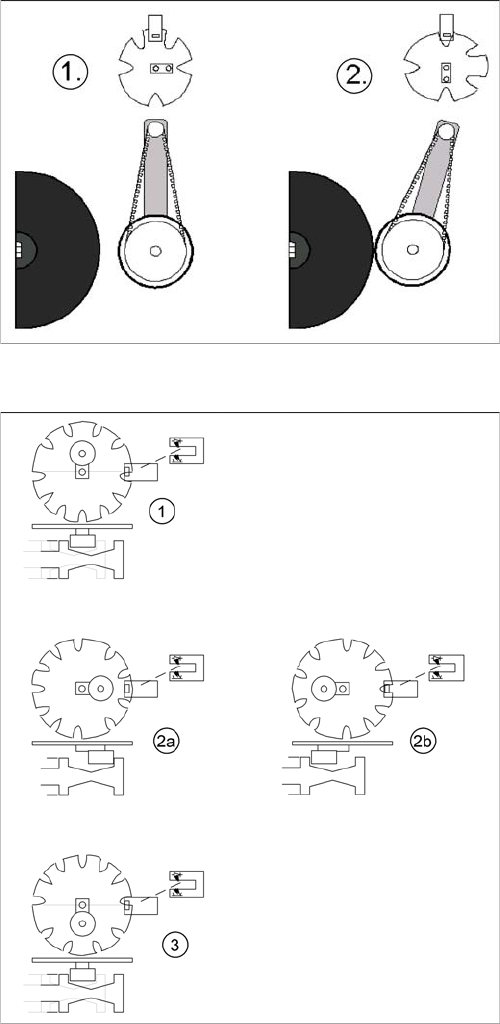
Initializing stepping motor at DP-station (1)
Legend
1. Home position DP drive around 1 mm away from seg-
ment
▪ The DP station has swiveled approx. 1 mm away
from the segment.
Initializing valve positioning drive at pickup/placement
and reject position
Legend
▪ 1. Home position, initial position. Release star axis
movement.
or
▪ 3. Counter position to initial position. Release star
axis movement.
▪ The valve positioning drives have positioned the drive
ball bearings in the valve plunger so that star rotation
without malfunction is possible.