80S-15贴片机.pdf - 第131页
SIPLACE 80 S/ F/G Service M anual 5 Gantri es Edition 04/97 5 - 13 5.4 Replacing the Drive Motor of the Y Axis 5.4.1 Spare Parts, Auxiliary Materials and Equipment – 1 motor for the y axis, comp lete, from item n o. 0030…
5 Gantries SIPLACE 80 S/F/G Service Manual
Edition 04/97
5 - 12
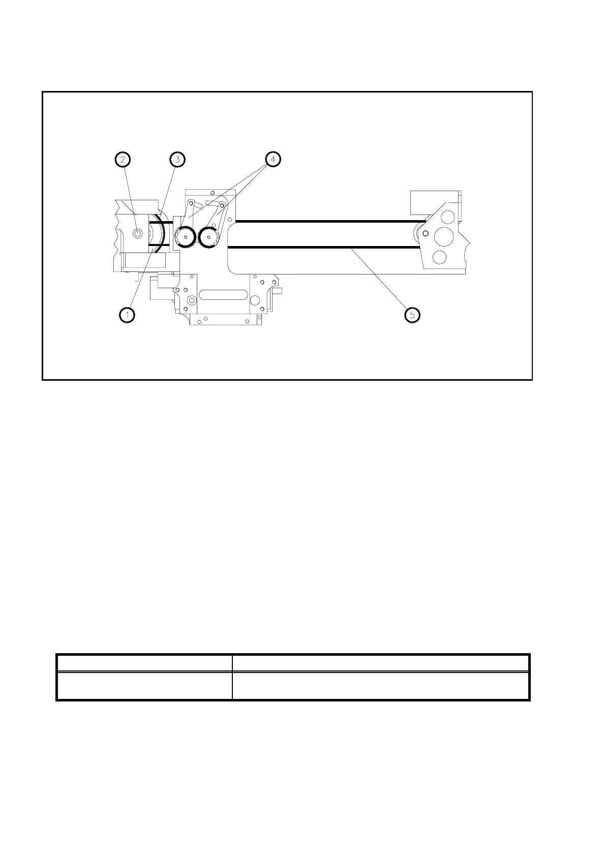
Fig. 5.3.1 Replacing the cut toothed belt of the x axis
Key to Fig. 5.3.1.
5.3.3 Installation
●
Insert the new endless toothed belt and fit the belt wheel.
●
Fit the x-axis cut toothed belt.
●
Mount the x-axis drive motor (see Section 5.2.3).
●
Tension the endless toothed belt in accordance with Table 5.2 - 1, Page 10 and the cut toothed belt in
accordance with Table 5.3 - 1.
●
Fit the placement head. After this adjust the placement machine.
1 Belt wheel 2 Belt wheel shaft
3 Endless toothed belt 4 Turnbuckle
5 Cut toothed belt
Toothed belt Cut toothed belt 32AT5 1755
Adjustment with belt tension measuring
device
Frequency prior to cont. operation Frequency after cont. operation
42 Hz ± 1Hz 39 Hz ± 1Hz
Table 5.3 - 1 Required setting for the x-axis cut toothed belt

SIPLACE 80 S/F/G Service Manual 5 Gantries
Edition 04/97
5 - 13
5.4 Replacing the Drive Motor of the Y Axis
5.4.1 Spare Parts, Auxiliary Materials and Equipment
–
1 motor for the y axis, complete, from item no. 00303631-02
–
Belt tension measuring device, from item no. 00326015-01
5.4.2 Removal
NOTE
OOO
You should comply with the safety instructions in Section 1.
●
Move the gantry out of the working area to prevent any damage to it.
●
Disconnect the components table cable and remove the components table.
●
Remove the empty tape cutter by undoing the four mounting screws and disconnect the connection cable.
You will only need to do this with SIPLACE 80S machines.
NOTE
OO
While you are carrying out this work be careful not to damage or dirty the scale and the reading head.
Clean soiled scales as described in the maintenance instructions.
●
Remove the lateral sliding plate holder together with the sliding plate.
●
Remove the components table support.
●
Loosen the y-belt at the tension rollers using the hexagon socket screw key, size 8.
●
Undo the two M6 mounting screws and remove the motor.
●
With gantry 1, disconnect the electrical connections of the motor unit. In the case of gantry 2 the electrical
connections are located behind the main switch.
NOTE
The motor is supplied as a complete unit consisting of the motor itself, the tachometer and motor pinion and
for this reason should also be replaced as a complete unit.
5 Gantries SIPLACE 80 S/F/G Service Manual
Edition 04/97
5 - 14
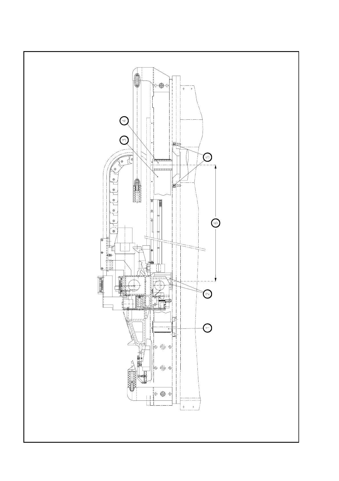
Fig. 5.4.1 Y-motor unit