80S-15贴片机.pdf - 第144页
6 PCB Han dling SIPLACE 80 S/F/G Servic e Manual Edition 01/96 6 - 8 Fig. 6.2.1 Removing the geared m otor of the input or center conv eyor Key to Fig . 6.2.1 1 Input conv eyor 2 Ce nter conv eyor 3 Output conv eyor 4 Ge…

SIPLACE 80 S/F/G Service Manual 6 PCB Handling
Edition 01/96
6 - 7
6.2 Geared Motors of the
PCB Transportation Systems
6.2.1 Replacing the input and center conveyor geared motors
Spare parts, auxiliary materials and equipment
Geared motor with synchronizing disk, Item No. 00324405-01
SITEST program
6.2.1.1 Removing the geared motor from the input and output conveyors
NOTE
OOO
You should also comply with the safety instructions given in Chapter 1.
●
Select the maximum width setting for the board conveyor so that you can carry out servicing work unim-
peded.
●
Move the gantry or gantries to outside the board transportation area.
●
Switch off the machine at the main switch and disconnect it from the main power supply.
●
Make sure that the machine cannot be switched on while you are carrying out servicing work.
●
Mark the installed position of the geared motor and also label the cable connections as protection against
incorrect polarity upon reinstallation.
●
Remove the cable shoes from the motor terminals.
●
From the conveyor motor strip the heat-shrinkable sleeves which fasten the connecting cable.
●
Unscrew and remove the 4 mounting screws (4 M3 slotted head screws) of the geared motor (A).
●
Tilt the geared motor a little to one side while carefully pulling the geared motor backwards and out (B).
Make sure that the synchronizing disk does not catch in the toothed belt.
6 PCB Handling SIPLACE 80 S/F/G Service Manual
Edition 01/96
6 - 8
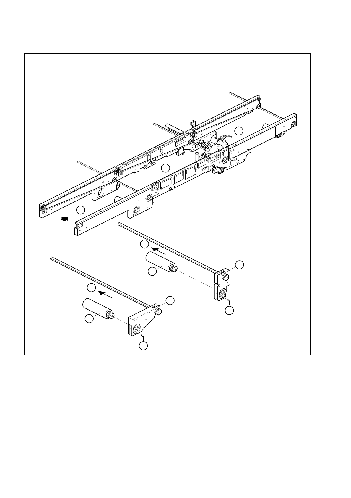
Fig. 6.2.1 Removing the geared motor of the input or center conveyor
Key to Fig. 6.2.1
1 Input conveyor 2 Center conveyor
3 Output conveyor 4 Geared motor
5 Input conveyor motor mount 6 Center conveyor motor mount
3
1
2
4
4
5
6
B
A
A
B

SIPLACE 80 S/F/G Service Manual 6 PCB Handling
Edition 01/96
6 - 9
6.2.1.2 Fitting and testing the input and center conveyor geared motors
●
Insert the new geared motor. Make sure that the toothed belt is positioned correctly around the synchroniz-
ing disk.
●
Mount the geared motor using the 4 M3 slotted head screws.
●
Refer to the circuit diagram folder to make sure that you have connected the motor up correctly.
●
Attach the power supply cable with the two heat-shrinkable sleeve rings.
●
Referring to the adjustment instructions, carry out a function test of the conveyor.
NOTE
OOO
While carrying out the function test do not fail to observe the safety instructions in Chapter 1.
●
Unlock the key-operated switch before performing function testing and making adjustments. This will allow
you to take measurements at the motors with the protective cover open. However the gantry axis systems
will be in a de-energized state.
NOTE
OO
When you have finished the function test do not forget to lock the key-operated switch again, stowing the
key in a place where unauthorized persons have no access to it.
6.2.2 Replacing the output conveyor geared motor
Spare parts, auxiliary materials and equipment
Geared motor with synchronizing disk, Item No. 00324405-01
SITEST program
6.2.2.1 Removing the geared motor from the output conveyor
NOTE
OOO
You should also comply with the safety instructions given in Chapter 1.
●
Select the maximum width setting for the board conveyor so that you can carry out servicing work unim-
peded.
●
Move the gantry or gantries to outside the board transportation area.
●
Switch off the machine at the main switch and disconnect it from the main power supply.
●
Make sure that the machine cannot be switched on while you are carrying out servicing work.
●
Mark the installed position of the geared motor and also label the cable connections as protection against
incorrect polarity upon reinstallation.
●
Remove the cable shoes from the motor terminals.
●
From the conveyor motor strip the heat-shrinkable sleeves which fasten the connecting cable.