80S-15贴片机.pdf - 第163页
SIPLACE 80 S/ F/G Service M anual 6 PCB Handling Edition 01/96 6 - 27 6.5.2 Fitting the retainers and compression springs The re tainers and compr essio n spr ings sh ould b e fitted bac k in the reve rse seq uence of op…
6 PCB Handling SIPLACE 80 S/F/G Service Manual
Edition 01/96
6 - 26
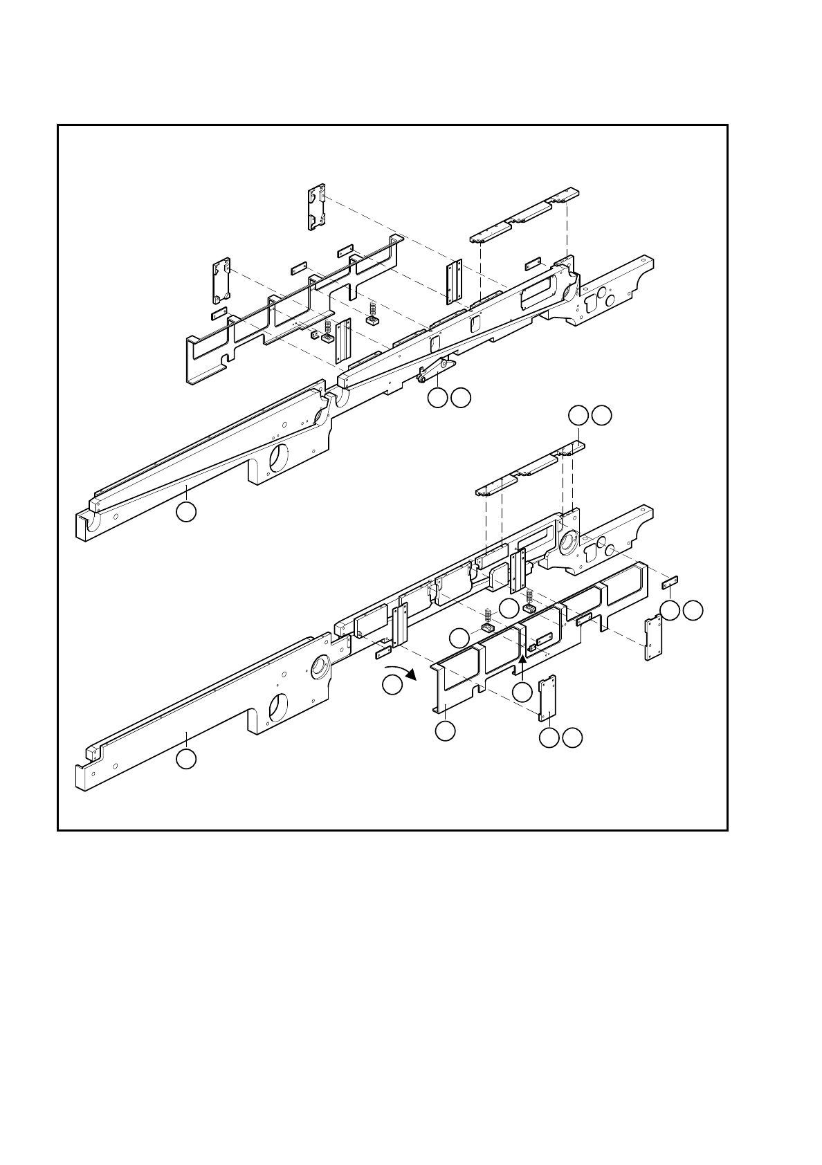
Fig. 6.5.1 Removing the retainers and compression springs
Key to Fig. 6.5.1
1 Side panel, fixed side 2 Retainer
3 Comb guide 4 DU strips
5 Guide rail 6 Compression spring
7 Block 8 Rocking lever
9 Side panel, movable side
1
9
2
4 B
5 E
7
6
F
8 A
3 C
D

SIPLACE 80 S/F/G Service Manual 6 PCB Handling
Edition 01/96
6 - 27
6.5.2 Fitting the retainers and compression springs
The retainers and compression springs should be fitted back in the reverse sequence of operations.
NOTE
Before fitting the compression springs check their length. When unloaded they should be 32 mm. If this is not
the case change the springs, always doing so in pairs for each side of the conveyor.
●
Align the guide rails as described in Section 6.6, Page 6 - 29.
6.5.3 Function test
Under the
Conveyor functions
menu carry out a function test with the boards.

6 PCB Handling SIPLACE 80 S/F/G Service Manual
Edition 01/96
6 - 28