80S-15贴片机.pdf - 第167页
SIPLACE 80 S/ F/G Service M anual 6 PCB Handling Edition 01/96 6 - 31 6.7 Lifting T able 6.7.1 Removing the liftin g table NOTE OOO You sho uld al so compl y with the safety instruct ions in C hapter 1. ● Select the max …

6 PCB Handling SIPLACE 80 S/F/G Service Manual
Edition 01/96
6 - 30

SIPLACE 80 S/F/G Service Manual 6 PCB Handling
Edition 01/96
6 - 31
6.7 Lifting Table
6.7.1 Removing the lifting table
NOTE
OOO
You should also comply with the safety instructions in Chapter 1.
●
Select the maximum width setting for the Board conveyor so that you can carry out servicing work unim-
peded.
●
Move the gantry or gantries to outside the board transportation area.
●
Switch off the machine at the main switch and disconnect it from the main power supply.
●
Make sure that the machine cannot be switched on while you are carrying out servicing work.
●
Slacken off the M 1.5 hexagon socket screws at the rocking levers and remove the ball bearing (A).
●
Lift the lifting table plate vertically upwards and off (B).
CAUTION
OO
The lifting table plate is heavy.
●
Make sure that you do not tilt the lifting table as you lift it out, otherwise you may bend the guide columns.
●
Set the lifting table plate face downwards on a flat and clean surface.
NOTE
O
Do not place the lifting plate on its side. Do not rest it on the guide columns. This could bend the guide col-
umns.
6 PCB Handling SIPLACE 80 S/F/G Service Manual
Edition 01/96
6 - 32
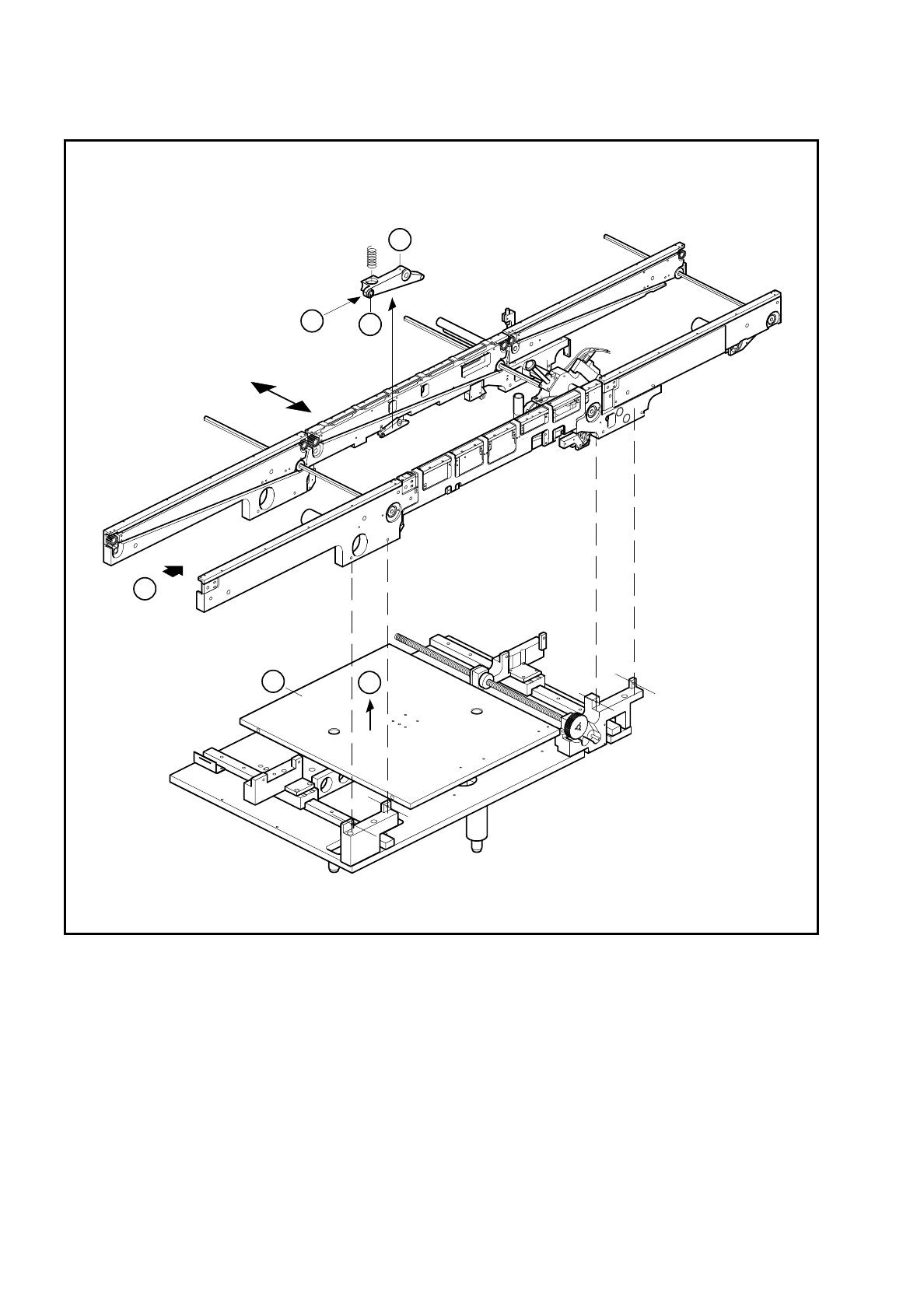
Fig. 6.7.1 Removing the lifting table
Key to Fig. 6.7.1
6.7.2 Fitting the lifting table
●
Insert the guide columns into the guide tubes (A).
●
Allow the lifting table to slide slowly downwards.
1 Rocking lever 2 Ball bearing
3 Lifting table
T Direction of board transport
3
T
B
A
2
1